
X-Rite i1Pro 2 also supports the following filter conditions conform with ISO 13655:
•M0: non-specified illumination (measurement used to date)
•M1: D50 daylight illumination (optimal illumination of new standard)
•M2: UV cut filter (IC-NG, fluorescent whitening agents in papers have no impact)
In this case, the device has an additional UV LED and a position sensor.
The status LED on the device guides you through measuring: White = ready to measure, green = measurement successful.
Note: If necessary, you must open the base plate before calibration.
Strip and spot (single) measurement are supported as well as measurement with an automatic measuring table. In strip measurement with an automatic measuring table, there are restrictions with regard to the patch sizes.
X-Rite i1Pro 2 can run in three modes:
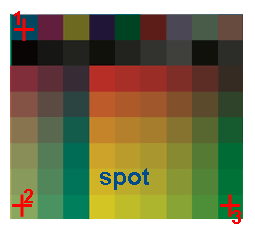
•Spot (single measurement)
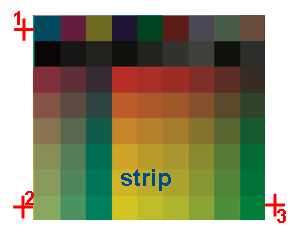
•Strip (strip or scan mode)
•IO (as a chart device on the measuring table)

Note: IO devices before the E series only support the M0 measurement condition in the strip mode. M1 and M2 can be processed only in the spot mode.
While M0 can measure in one run, M1 and M2 need two runs. The internal UV LED switches on during the second run. In a single measurement and with the automatic measuring table, this switching happens so fast that no significant difference in time can be noticed. On the other hand, in the scan mode two separate scans are needed to measure using M1 and M2 conditions.
During a spot measurement for M1 and M2, the two internal illumination runs are done in succession unnoticed by the user. For that reason, with M1 and M2 you should wait until the status LED switches to white again before measuring again.
Measure with tray and scan ruler
Besides using X-Rite i1Pro 2 with the automatic measuring table, you can also operate it with a tray and scan ruler. The position sensor in conjunction with the strip on the scan ruler makes measurement of smaller patches possible and, consequently, the double scan runs mentioned above that are required for M1 and M2. The tray and scan ruler are essential for measuring in the scan mode with M1 and M2.
Scan process for M1 and M2:
Important: When scanning, start before the first patch to be measured and finish after the last one.
1.Status LED white = ready to measure
2.Press the measure button, the LED goes out = ready for the first scan run
3.After the first scan run: Status LED green (briefly) = first measurement successful
4.Status LED blue = ready for second scan run (LED lights up on one side to indicate direction)
5.Press the measure button again, LED goes out = second scan run (with UV LED) can start
6.Status LED green (briefly with additional ring tone) = measurement successful
7.Status LED white = ready for new measurement
•Status LED red (briefly) = measurement not successful, e.g. scan too slow or too fast or automatic internal synchronization of both runs failed
Notes:
•It is extremely important that the positions of the start and end patches are not changed during scanning so that the measured patches can be synchronized with each other.
Scan start: in white before the first patch
Scan end: in white after the last patch
•The tray is too small for minispots ECI_BVDM_TVI_10 and ECI_GrayConL.
•Field work has shown that the two scan runs cannot always be coordinated exactly and this results in faulty measurement results. For that reason we recommend that you measure the data twice to be sure.

Caution: Make absolutely sure that the scan ruler is inserted the right way round into the tray because your results will be back-to-front if this is not the case.
Using the IO device as of the "E" series, you can measure both in the slower but flexible spot mode and in the faster strip mode in M0 thru M2 (in both cases, single illumination in M0 and double illumination in M1 and M2).
Remember the following items when using the device:
•Restrictions in the size of the patch to be measured
The new strip mode supports only patches greater than 6x6 mm and as a result is released only for:
·UGRA/FOGRA MKV3
·IDEAlliance (Type 2013)
·In addition, you can also use the strip mode with G7-P2P25/P2P51.
•Different positioning during initialization
·In the spot mode, the device must be positioned in the middle of the patches at the top left, bottom left and bottom right.
·In the strip mode, the device must be positioned on paper white to the left of the topmost and bottommost left patch and then to the right of the bottom right patch.
•Note about G7-P2P25
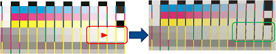
·The contrast in G7-P2P25 is too low for the strip mode, resulting in the yellow separating line not being detected correctly in rows 4 and 5 for the five light patches. You must blacken these separating lines for measuring in the strip mode (does not apply with P2P51).
•Test charts for IT8.7-4 CMYK i1_iO_1_2 and IT8.7-4 CMYK i1_iO_2_2
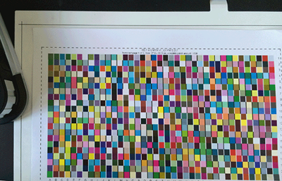
You must use a special chart to measure IT8.7-4 in the scan mode in M0 (can be found in "...\Testcharts\Testcharts PDF\ISO 12642-2 (IT8.7-4) Charts\i1-iO"). To measure, position both pages with the text at the top position (see illustration).
To measure in the spot mode, use the standard test chart installed with Color Tool.
Overview of the supported measuring processes with the IO.
|
IO Mode |
Measurement Condition |
Elements |
Positioning |
|---|---|---|---|
|
Spot |
M0 - M2 |
All |
Old method (in the middle of the patches) |
|
Scan |
M0 |
Test charts with 6x6 mm |
Old method |
|
Scan |
M0 - M2 |
FOGRA MKV3 (7x7mm) |
New method (on paper white beside the patches) |
* see Different positioning during initialization
The Assistant automatically toggles between the positioning methods, depending on the selected parameters and elements.