
Note: Some of the settings in this tab require the "Packaging Pro" and/or "Label Pro" licenses.
This is where you can set the folder for shapes and cutting dies.
In the "Packaging" step, you can copy cutting dies under the specified Tool ID directly to the "... > CAD Files > AutoToolPool" subfolder with the "Save as CAD file to the Tool Pool" function. In this process, the Tool ID is used for the file name. Cutting dies of the same name that are already in the folder are not overwritten.
The option defines the cutting line type, for example, line type 99 that is usual in packaging.
This is where you can set defaults for creating new cutting dies.
•Bleed for Shape
•Min. Spacing between 1ups
•Orientation Default for Label: This lets you set an orientation default for the single 1ups. The following values are possible for the orientation default:
·0 degrees
·90 degrees
·180 degrees
·270 degrees
·0 or 180 degrees
·90 or 270 degrees
·0, 90, 180 or 270 degrees
·Free Rotation
The value for the orientation default then displays in the Nesting Wizard of LabelPro. The "90 or 270 degrees" value is presently not supported by LabelPro. It is switched to "0, 90, 180 or 270 degrees".
CAM/CNC Machine (only with the "Label Pro" license)
For a CAM/CNC machine output in Label Pro, the files are written to the folder set here in the Preferences. The "CAM/CNC Machine" option must be enabled for this.
Machine Type: List box for selection of a CAM/CNC machine
Path for CAM: Folder where the file for the CAM/CNC machine will be filed.
Dielines (only with the "Label Pro" license)
Register marks and cutting data are needed for the digital punch to be able to cut the 1ups correctly on the press sheet. Positioning of the laser is possible using the register marks. The cutting data are available in the CFF2 as lines with a predefined line type. In addition to cutting as a processing step, creasing, perforating and cutting and creasing are also possible as processing steps.
A CFF2 is available if a packaging job is processed in Signa Station. This CFF2 contains lines that are each assigned to a type.
In the Preferences, a processing step for finishing and a color can be assigned to the line type.
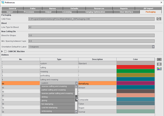
The processing steps are assigned to a line number in the "Type" column by selecting one from a list with names compliant with the standard ISO19593-1.2 In the "Description" column, you can enter any explanatory text, for example, if you usually use a different name for the processing step.
You can create more line types using the plus button. You can remove line types that are not needed by marking them and clicking the trashcan button.
Register marks for later register of the sheet on the machine can be added automatically to the cutting die. "Cutting Die Register Marks" is available for this in the "Marks" step.
When a job like this is output from Prinect Signa Station to the Prinect Cockpit, the line types assigned to processing steps and colors with the full CFF2 are written to the PDF marks layer. In addition, the positions of the register marks are written to the JDF. In this process, all marks are considered register marks that have "Register Mark" as the mark type or were set as "Cutting Die Register Marks". In the JDF, these are in the layout compliant with the JDF specification.
In the Prinect Cockpit, the additional colors "CFF2-Creasing" and "CFF2-Cutting" with "Tool" as the usage can be seen for finishing.
For output in the Prinect Cockpit, there must be an ImpositionOutput or ImposedPrint sequence in addition to the Qualify sequence in "Processing". The "Tool" must be enabled in the setup for this so that the colors of the "Tool" usage are also included in the output.
You can open the PDF generated this way in Adobe Acrobat that shows the inserted "CFF2-Cutting" and "CFF2-Creasing" optional content groups as layers in the colors defined in Prinect Signa Station. Line types that are in the CFF2 but are not assigned to any concrete processing step can be grouped in the "CFF2-Unknown" optional content group.
Display color
In addition you can define the color that is used to display the line types.

|
To edit the colors, select the line color you want to change from the list and click the button with the color icon. |
The "Select Line Type Color" dialog then displays, where you can set the color you want using the slider or the text boxes. "Default" lets you reset the color values back to the original default settings, use "Reset" to restore the values last saved for a color.
