Packaging (only in the "Packaging" work mode and in "Sheet Optimization for Packaging")
The "Packaging Pro" and/or "Label Pro" license is a prerequisite in Prinect Signa Station for the "Packaging" step. We will explain the functionalities in this step in the sections below.
You can find a description of how to work in the "Packaging" work mode in Packaging (Packaging Pro, Label Pro).
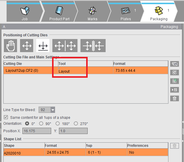
Cutting Die File and Main Settings
The table shows all loaded cutting die files with file name, tool and format. You have the option of changing the tool ID in the "Tool" box.
Positioning of Cutting Dies
The settings for the positioning of cutting dies are kept permanently. This allows the positions of the cutting dies to be restored automatically after changes to the job (e.g. change in paper size).

|
manual positioning There is no automatic mechanism for the positioning of the cutting dies. This condition is also valid whenever the position of a cutting die is edited manually, either by entering a value in the text box or by moving the cutting die in the graphic view. The data of the user interface elements below the table refer to the cutting die selected in the table above. Only if all the selected cutting dies have the same values do these also display. If the values differ, elements remain empty. |

|
centered horizontally and vertically on the paper All the cutting dies are distributed evenly in each direction and centered as a whole to the paper or half of paper. If this is not possible because there is not enough space, then the cutting dies are arranged one below the other and centered to the paper or half of paper. |

|
centered horizontally on the paper and vertically on the gripper margin |

|
centered horizontally and vertically on both halves of the paper |

|
centered horizontally on both sides on a "virtual" gripper margin and vertically on both halves of paper |
|
|
The "virtual" gripper margin is an imaginary area if the paper would be cut through the vertical center and a gripper margin would be applied to the resulting cut edges. The cutting dies are positioned on both sides of the "virtual" gripper margin. |
Button functions

|
Folder button |

|
PackagingPro button |

|
LabelPro button |

|
Save CAD file |

|
Save CAD file to AutoToolPool |

|
Trashcan button |
•It is also possible to set a default folder for CAD files in "Preferences > Packaging" if you are working with cutting die files.
You can also load a cutting die file with drag-and-drop. See Drag-and-Drop for details.
Apart from details about the files, the table also displays all contours of the cutting die in the "Contours" column (number of contours in brackets), and in the "Relevance" column a percentage indicating how well the cutting die fits the contours demanded by the Multiple Sheet Optimizer (only if the Multiple Sheet Optimizer is enabled).
You can also view the shape by selecting the related tab above the preview window.
In the "Line Type for Bleed" list box, you can select the line types available for the selected cutting die.
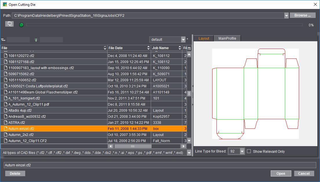
Besides the most frequently used files of type CF2, CFF and CFF2, you can also load or import other types of CAD files as cutting dies. Basically, there are three different procedures when opening the cutting die file:
·Cutting die files of type *.cff, *.cf2 and *.cff2 that were created, for example, with Prinect Package Designer or ArtPro.
You can load these files directly to Signa Station. You only have to open a correct CFF2 cutting die with Packaging Pro if you want to create a PDF 3D or specify the trim on the sheet layout.
·Cutting dies of type *.evd created with Prinect Package Designer
Packaging Pro opens automatically when such cutting die files are loaded and displays the single side and sheet layout. Normally, after checking the data, you can copy these files to Signa Station simply by clicking "OK".
·Other vector-based formats like, for example, AutoCAD files of type *.dxf or *.dwg, *.ai files created with Adobe Illustrator, DieCAD files (*.n), DDS (*.dds, *.dde, *.ds2), PDF, EPS/PS and Windows meta formats (*.wmf, *.emf)
Here, too, Packaging Pro launches automatically for the import. You first see the "Import Preview" window where you can set various filters for the import, for example, which line types will be assigned to cutting, creasing, etc. After the import, the die first displays in Packaging Pro where you can revise and correct data (e.g. incorrectly defined line type) and create the layout for the sheet.

Note: You will find details about these topics and working with Packaging Pro and Label Pro in their respective Online Helps that you invoke with the F1 key from that option or using the Help menu in Prinect Signa Station.
In the graphic window, the hulls of the loaded cutting die file have green lines.
Line Type for Bleed
The default value is "92".
All the lines of this type in the cutting die file are considered bleed lines. This should produce a closed path.
Same Content for All 1ups of a Shape
When this option is set, a hull (shape) is automatically assigned the same content. In the graphic window, you will see that all the hulls have the same number.
The numbers are incremented if the option is not set and if a hull has different content. In this case, you must assign the contents separately for each hull.
The cutting die selected in "File" is rotated counterclockwise by the selected angle on the paper.
Manual positioning is possible using "Position X" and "Y".
In addition, you can use the four buttons to position the cutting dies horizontally or relative to the center of the paper (useful when working with a separating cut) and vertically or with the gripper margin Positioning relative to the center is useful when working with a separating cut and is available only if multiple cutting dies are loaded.
Table showing the hulls of a cutting die file.
Each hull displays its name, styles (geometry data), number of 1ups and the defined presettings.
You can rename a hull manually and delete a selected one.

|
You will see the trashcan to the right of the table. You can use this to delete hulls that are no longer needed from the table. Deleted hulls are no longer shown in the graphic window. |
An accurate preview is calculated for each 1up (with all existing marks) when this option is enabled. You can disable it to save time when saving your data. In this case, a preview is created only of the first 1up.
Placement rule for assigned 1ups
This is where you define the placement for all the 1ups of the selected hull. The default in the "Packaging" mode differs from that in "Imposition" "By user" > "Center".