Work and Turn a gang sheet - Gang sheet designer
First, a few basic pieces of information need to be clarified.
Usually a gang run form is created in the "Sheet/Web Wizard".
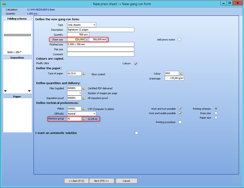
When creating a gang run form the dimensions of the sheet are asked for.
The sheet size is the printable area where the gang parts can be placed. This parameter is defined by the user in advance.
Some users do not even create gang parts. They do not need a detailed imposition in the calculation. Only a cost for paper and printing is required. Creating the gang parts is becoming very useful, because then the calculation is complete. The number of pages on the quote letter will be correct, the visual workflow is complete, ...
With the gang part designer you get a full description as it is available for normal print sheets. Gang parts can be created and positioned on the gang sheet. The exact positions of the folding schemes on the sheet are even transferred with JDF to the prepress tool.
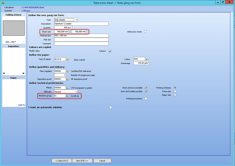
When creating a gang run form the dimensions of the sheet are asked for:
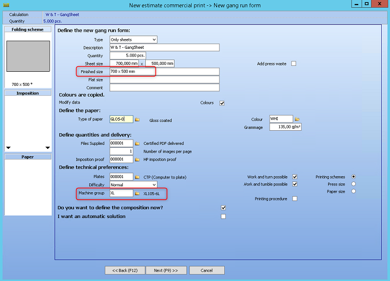

The "usable area" will be half of the gang sheet. The gang parts cannot be placed outside this area. The "usable are" is the finished size.
To avoid problems when generating the gang run form, it makes sense to define the corresponding machine group here.
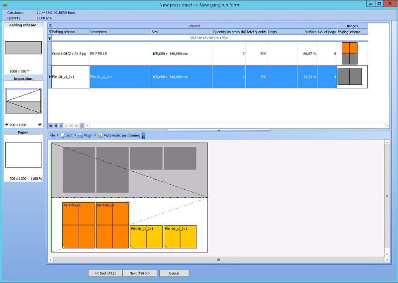
Example 1
A typical example is a gang sheet for 12 pages in a brochure where an 8 pager and a 4 pager are placed on the same sheet. The user can create the gang parts by choosing a folding scheme and providing the page sizes.
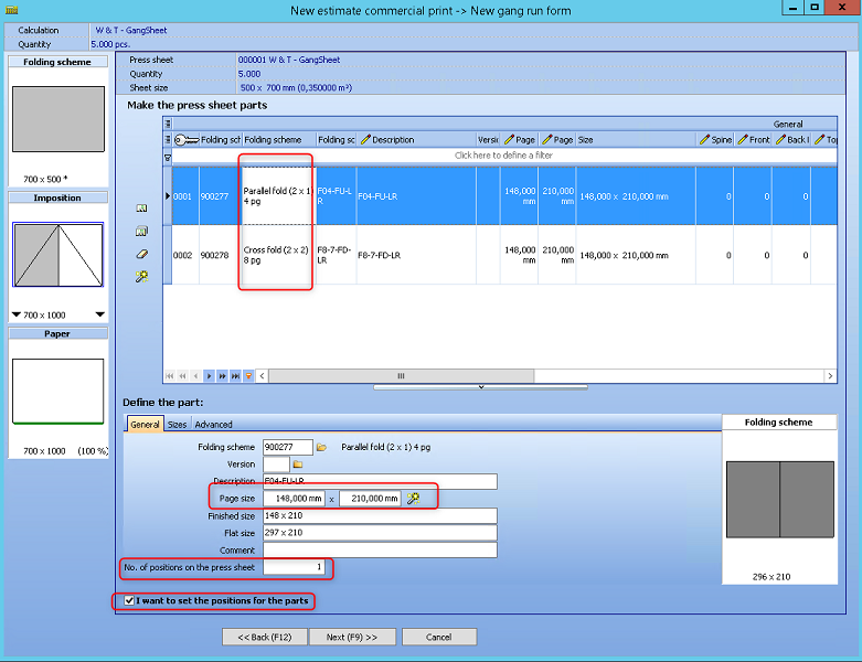
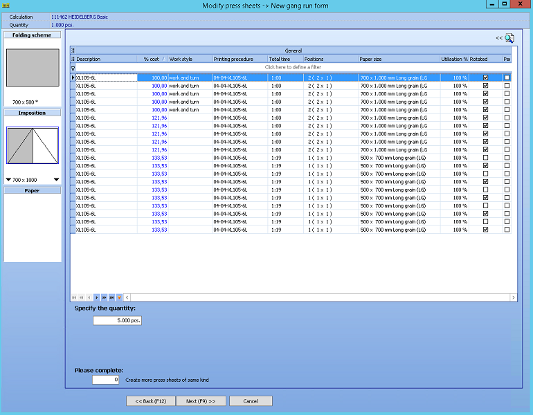
The system searches for the optimal print procedure. It can happen that the given surface is placed multiple times on a stock paper.
Due to the definition of the machine group in the first step, only the printing processes of the XL105-6L are displayed here.
The "usable area" will be half of the gang sheet. The gang parts cannot be placed outside this area. For all other poses, the gang part will be duplicated and put visible on screen as a dark grey box: a "shadow" gang part.
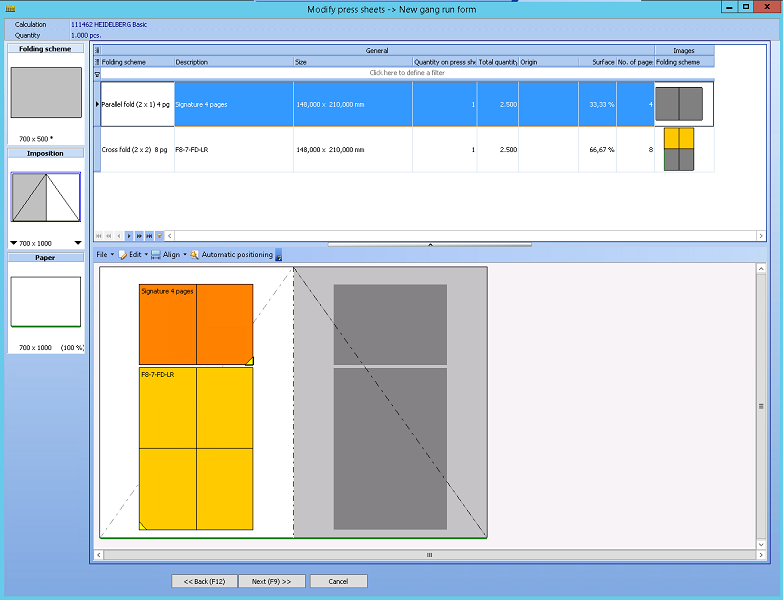
•Blue lines mark the "usable" area. This is the white area. The rest of the gang sheet is greyed out. Only the white area accepts positioning a gang part.
•The typical diagonal lines to indicate "work and turn" are added to the drawing (grey.)
•The shadow-poses are mirrored over the y-axis (work and turn).
•The shadow-poses are mirrored over the x-axis (work and tumble).
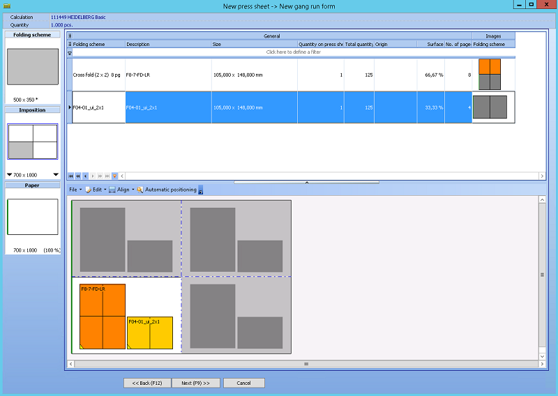
Example 2
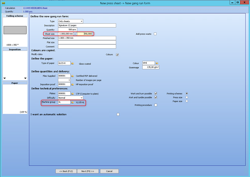
This example shows a gang sheet with multiple poses in "work and turn". The sheet size must be reduced here according to the maximum format. In this example, the sheet size is exactly 1/4 of the sheet to be printed.
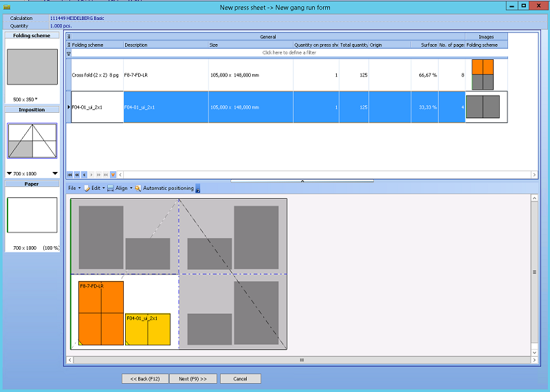
•Blue lines mark the "usable" area.
•The usable area for the user is the lower left pose.
•The typical diagonal lines to indicate "work and turn" are added to the drawing (grey.)
•The shadow-poses are mirrored over the y-axis (work and turn).
Example 3
Work and Tumble
•The typical diagonal lines for work and tumble are added to the drawing (grey).
•The shadow-poses are now mirrored over the x-axis.
•The usable area for the user is the lower left pose.
Example 4
As a next example we have a normal printing procedure, but with multiple poses.
•Blue lines mark the "usable" area.
•The shadow-poses are repeated on the same relative position, on all the other poses.
•Again the usable area for the user is the lower left pose.

Align the gang parts - All these functionalities work within the usable area.
The automatic positioning - The start position is currently always in the lower left corner.