
Click "Edit" to enable the edit mode. To create a user-defined printing standard, you can modify the nominal values and tolerances or the printing order of an existing process standard in the edit mode or use existing data from "Measure".
You can enable the density values that are not defined in the process standard and/or the CIELab values of the secondary colors and overprint. You must save the process standards under a different name because the process standards included in the shipment are write-protected.
Note: In "Preferences > MDS" you can choose whether the process standards will be saved locally or in the MDS (Master Data Store). In addition, you can set that the tonal values will be taken from Calibration Manager. This is always the case when you work with an external MDS.
You can migrate process standards that are saved locally to the external MDS.

Note: You can import the process curve set for multicolor process standards from Calibration Tool. But in this case you cannot edit the dot gain curves. You can edit dot gain curves only when you create and save process standards locally or when the option using Calibration Tool is disabled. If the option is enabled, you can edit dot gain curves only with Calibration Tool.
In the edit mode, select the process standard you want in the "Standard" and/or "Printing Material" lists. The following data displays in diagrams and data tables: dot gain, nominal values and tolerances of CIELab data plus any density values and the order of printing.
Default
You select the standard from two list boxes:
•In the left list box you select the process (CMYK, Multicolor or Spot colors).
•In the right list box you select the name of an existing process standard.
Type a name for the new printing standard.
Printing material
Use one of the default paper grades.
The various printing materials have different color data and tolerances. The following paper grades are defined for the Color Toolbox:
•PT1 - glossy coated white; PT2 - matt coated white
•PT4 - uncoated white
PS Norm Type
The "PS Norm Type" shows the type of the current process standard and can have the following values:
•Offset (indicates the well-known classic offset printing standard)
•Proof comprises the proof standards compliant with ISO 12647-7 (in predecessor versions, to be found in "Compare").
•Digital comprises digital printing standards compliant with ISO 15311.
•G7 comprises the American offset printing standards compliant with ISO 15339 or ANSI/CGATS TR016.
"Delta E Type" indicates which color distance formula is used by the currently selected process standard; it can have the following values:
•Delta Eab
•Delta E2000
The legacy offset standard ISO 12647-2:2007 that is used everywhere may only have the Delta Eab color distance formula, whereas the new offset standard ISO 12647-2:2013 generally uses Delta Eab but optionally can also support "Delta E2000".
The proof standard uses Delta Eab as its color distance formula.
The digital printing standard only uses Delta E2000, the new color distance formula.
The G7 offset standard uses Delta Eab as its color distance formula.
This item indicates which density status the currently selected process standard uses for measuring density and in turn also for determining dot gain. Older process standards do not specify the density status at all whereas the density is measured very accurately in newer standards.
Because the density status is specified in Color Toolbox in "Preferences > Measurement", it is advisable to check the density status of the standard against one's own measurement mode.
The internal reference file is important only for "Proof", "Digital" and "G7" standards. It is not important for offset printing standards.
Proof, digital printing and G7 process standards require an internal reference file for comparison. The current measurement is compared with this internal reference file and the deviations between the two are evaluated. This item describes which internal reference file is used by the currently selected process standard.
Comment
Enter more details about the name in this box if you wish a more precise description of the printing standard (e.g. details about the basis, backing, the defined printing materials). This comment appears as a tooltip in the tree structure of "Administration" and helps you decide which process standard is the one you need.
Show/Hide Dot Gain Curves
The dot gain is shown in a diagram in the edit mode. In Color Toolbox you can determine the dot gain in steps of 10% and also for the two reference points 25% and 75%.
When you create and save process standards locally, the curves for the three chromatic process colors Cyan, Magenta and Yellow (primary colors) are shown together. Black (K) is shown separately because it usually has higher deviating defaults. The small dots you see in the diagrams show you where the dot gain was determined.
When you import dot gain from Calibration Tool, all the colors will appear in a single diagram. Click the graphic area to switch to single views of colors or to go to the next curve. The corresponding color channels are shown to the right of the diagram.
Show/hide dot gain values
The dot gain value table shows the nominal values and tolerances for dot gain specified in the process standard in black; non-existing values are shown in gray. A color sample at the upper table edge shows the process colors.
•Std = defined dot gain of the process standard
•Tol = tolerance value
The nominal values are entered in "Std" (standard). You can define a tolerance (plus/minus standard) in the "Tol" (tolerance) box.
You can type the dot gain in 10% steps and also for the two reference points 25% and 75%. Usually, you define the tonal values at 40% and 80% and this is required for a process standard.
For the primary colors, you can also specify a value for the spread. The spread is the maximum difference between the three chromatic process colors (the maximum spacing in the graph). This value lets you define an additional limit. This means that the actual values are not in the process standard when this value is exceeded, even if the values are within the tolerance range.
Show/hide paper white
Paper white is specified separately because the tolerances for the L*, a* and b* values usually differ.
The tolerances relating to the process standard are entered separately in the table to the right as Δ values.
You can hide and show this view/input box as you like.
"Show/Hide CIELab color values and density values
If you wish, you can enter the L*a*b* values (solid tint) for all the colors if the appropriate color is checked. The tolerance is specified by the color difference ΔE* (color distance).

Note: The default values for secondary colors (red, green and blue) and overprint (CMY Gray) defined in older process standards are normally disabled because they are difficult to comply with technically.
Small color samples indicate the color. You can choose existing names in the list boxes or type them in the text boxes.
Similarly, you can also enter the final density values for the primary colors cyan, magenta, yellow and for black on the right side if the relevant boxes are checked.

Note: Although the process standards shipped with Color Toolbox have solid tint density values, all these values are disabled. This is because it is very difficult to specify density defaults due to varying measurement conditions. ISO standards do not have any binding density defaults because this parameter is not standardized and explicit.
You can enable these density values by checking the boxes. These default density values correspond to measurement conditions with a polarization filter. If necessary, you can overwrite these values.
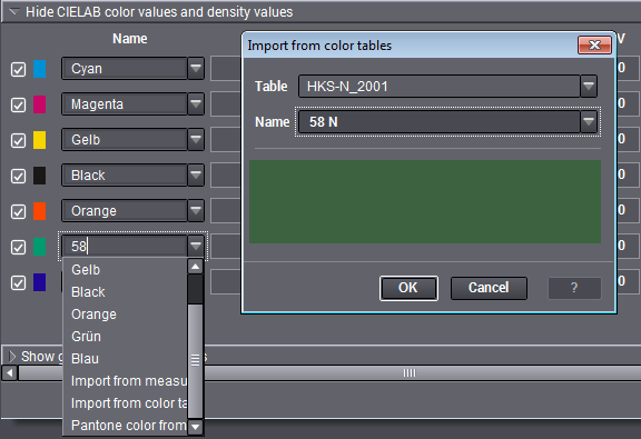
Three additional functions are available in the list boxes for the color patches when you select a Multicolor or Spot color process standard:
The "Import from color tables" dialog opens automatically when you select this item. Select the color table you want and then the color to be used. You can use the functions for a simple search in color tables (see Name).
To create new process standards for Multicolor/spot colors with measured color data, first select the desired patch on the measured test chart in "Measure > Test chart". Then select your new process standard in "Process standard" and in "CIELab color values and density values" the item to which you wish to assign the measured value. The values are applied with "Import from measured data"; you only have to customize the name of the color.
IMPORTANT: After every import of measured data, you must first save the process standard before you go back to "Measure" to select another color patch for import.
•PANTONE® color from measured data
The function combines the "Import from measured data" and the color table: Like in "Import from measured data", you first select the desired color patch on the measured test chart in "Measure > Test chart". Then select your new process standard in "Process standard" and in "CIELab color values and density values" the item to which you wish to assign the measured value. When you choose "Pantone color from measured data", the data of the color patch selected in "Measure > Test chart" are used for the automatic search for the spot color whose values are closest to the measured data. The "Import from color tables" dialog then opens automatically, showing you the spot color found. When you click "OK" in this dialog, this spot color is then used as a new primary color, and the Lab values of the color table are set for this new primary color.
IMPORTANT: Like with the import of measured data, you must first save the process standard before you go back to "Measure" to select another color patch.
Show/hide print order
The order of printing defined for the process standard is shown by a press with a maximum of eight printing units. Active printing units are numbered from right to left and marked by the respective colors.
You can modify the printing unit setup by clicking the printing unit colors. The color changes each time you click.
Click through to the color you want for every printing unit, going from right to left.

Note: This is shown for your information only and will not be gone into detail.
Use values from measuring area
The current color data of the test chart or control element open in "Measure" are automatically entered as the reference data (standard) as well as the tolerances when you click "Use measurement values".
You can also enable "Use tonal values, if available".

Note: You can delete a user-defined printing standard only in the view mode or in the "Administration" view.