
You can open the "DeviceLink profile" dialog using the "Tools" menu in all the main functions. Two CMYK device profiles are connected to a DeviceLink profile in this dialog. RGB profiles are also possible. You can also set special options for keeping black plus CMY and RGB colors in this dialog.
Calculation of DeviceLink profile
DeviceLink profiles describe the reproduction properties of an entire process chain. You can use them, for example, to simulate newsprint on a proof system.
In the method used in this case, the DeviceLink profile will be calculated from existing profiles of the two processes or print conditions. Total dot area and gamut mapping can be taken from the press profile, and black can be set with the appropriate parameters.
First of all, the profiles you want to link are opened. "Profile 1" is the profile that describes the color space of the input device and "Profile 2" is the profile that describes the color space of the output device.
Following that, the options for totaling the profiles are selected (rendering intent, preserve black, preserve colors and black point compensation).
Profile 1
Click "Open" to open the profile browser where you can select and open a source profile.
Profile 2
Click "Open" to open the profile browser where you can select and open a target profile.
Rendering Intent
Then select one of the four rendering intents for this target profile. The rendering intent defines the approach taken in color reproduction (see Rendering Intent for a description).
During a device color space conversion, you can select four different options for keeping black:
•None: Black of the source profile (Profile 1) is not preserved and is replaced by that of the target profile (Profile 2). This is always a good idea if the processes differ a lot, for example, going from offset printing (chromatic reproduction) to newspaper printing (achromatic reproduction).
•K=K: Black remains identical. Only the chromatic colors C, M and Y are converted to the target CMY color space, K is not converted, so that the hue effect is kept as far as possible. This option makes sense, for example, whenever one of the chromatic process colors is to be replaced by a similar color and all the other process conditions are to stay the same. This setting is also ideal for documents with a large amount of text and line art. Through "K=K", you can avoid that black elements suddenly have a considerable amount of chromatic colors. The total dot area of the output profile is NOT preserved in this process! For example, CMY 100%, 100%, 100% becomes 95%, 100%, 85% + 100% black.
Note: This setting can cause problems during output if the black inks have different densities in the source and target color spaces.
•Basic: Like with "K=K", C, M and Y are converted to the target CMY color space, K is converted to the target density with the help of a gradation curve. This setting is also ideal for documents with a large amount of text and line art (grayscale images). The gradation curve solves any problems you may have with differing black ink densities. The total dot area of the output profile is NOT preserved in this process! For example, CMY 100%, 100%, 100% becomes 95%, 100%, 85% + 100% black.

Note: With this method, it is possible that a 100% black may not be reached and text and graphics may be reproduced inadequately in some cases.
•Special (default): This is a special setting that works as follows:
·C, M, Y are converted to the target CMY color space for mid-range and light hues. K is converted by means of a gradation curve. The lightness curve is kept in this process.
·A special four-dimensional model keeping K is used for dark hues. The original black is kept in the shadows. The chromatic colors are converted in such a way that color perception is preserved as far as possible.
The overall performance is a mixture of the "None" and "Basic" settings in "Keep Black". Extensive tests have shown this procedure to be the best. The "Special" parameter eliminates most of the problems in complex documents. This parameter is only provided by the HEIDELBERG CMM. This setting is suitable for documents with text, color and gray images. The total dot area of the output profile is preserved.
Preserve colors
You can choose from five different options for keeping colors when creating DeviceLink profiles:
•None: The colors of the primary and secondary tonal values of the DeviceLink profile are taken from "Profile 2", the press profile. The color composition of the input profile is overwritten. This is always meaningful when the processes differ greatly from each other.
•Primary The solid tints of the primary chromatic colors (cyan (C), magenta (M) and yellow (Y)) are kept.
•Primaries and tonal values: The smooth shadings (blends) are preserved as well as the solid tints. These are single-color tonal gradations of the chromatic colors going from 0% to 100%.
•+ Secondary: In addition to the solid tints of the primary chromatic colors (cyan, magenta and yellow), the two-color overprints red (MY), green (CY) and blue (CM) plus the overprints of a chromatic color with black (CK, MK, YK) are preserved.
•Secondaries and tonal values: The two-color smooth shadings of the chromatic colors or of a chromatic color plus black are preserved in addition to the primary colors (cyan, magenta and yellow) with single-color smooth shadings and the secondary colors (red, green and blue).
You should prefer this setting in day-to-day operations when you want to save chromatic inks and preserve the overprint properties by creating special color compositions in the data to be printed (achromatic composition).
•+ Tertiaries with K setup Colors that are composed only of two primary colors (CY, CM or MY) and black are ignored by color management and stay as they are in this composition. This means there is no four-color setup following conversion.
Such colors are mainly used in logos or similar cases where an accurate adoption of the color data is desired.

Note: If "Preserve colors" is not used, when the DeviceLink profile is being generated, color management sees to it that the Lab value of a contone value in the first process is reproduced as accurately as possible in the second process. However, this colorimetrically correct transformation can result, for example, in an orange made up only of yellow and magenta having a small amount of cyan after the DeviceLink profile is applied. Because these amounts are often perceived as disturbing especially in diagrams, you can enable the option for keeping the color coordinates for at least secondaries and tonal values: a contone value that contains only two chromatic colors is not affected by the DeviceLink.
You can also customize the lightness curve when preserving colors using the "Primaries and tonal values", "+ Secondaries and tonal values" and "+ Tertiaries with K setup" settings.
The aim of this function is to create DeviceLink profiles between similar print processes that basically differ in their dot gain, for example, the conversion from isoCoated CMYK data to an offset process with non-periodic screens.
If the input and output profile have very different dot gain curves, this can cause the gradation of the curves to change. The different dot gain is taken into account when you enable "Customize lightness curve". In this case, the CMYK coordinates are no longer kept exactly as they are but a contone value consisting only of two chromatic colors is built up with only these two chromatic colors after the DeviceLink profile is applied.
The function matches the screen percent of each channel so that lightness from the input process is kept as good as possible. For example, this can result in a contone value CMYK = (50%,30%,0%,0%) being converted to a contone value CMYK = (55%,38%,0%,0%) for the output process. "Normal" color management is applied again in the center of the color space and the transitions are smoothened as is usual when preserving colors.
This option enhances the detail contrast in image elements that are made up solely of K. The contrast is increased by adding cyan but without a color cast becoming noticeable. You can choose between three different levels. "30% Cyan" means that areas with 100% black are given a supplementary 30% cyan. Cyan decreases more rapidly than K, meaning that the cyan value is already at zero if you have a middle K value.
Higher cyan values produce a higher contrast. In practice, values of 30% or 60% are sufficient in most cases. Objects made up of more than one color are not affected by this setting. This means that the option normally does not affect color images at all.

Caution: Because text is handled just like graphics, the addition of cyan also affects pure text elements. For that reason, you must define the appropriate settings in the PDF Toolbox if such a profile is used for printing pure black text elements.
The "Black point compensation" option is only effective in combination with the "Rel. colorimetric" rendering intent. With this option, the different shadows (the maximum achievable four-color black in the print) in the input and the output processes are mapped to each other. The same is done with the chromatic colors. This makes black point compensation a special form of gamut mapping (linear gamut mapping). Apply this option is feasible if the gamut differences between two processes are not too great and the objective is to obtain a reproduction as uniform as possible.
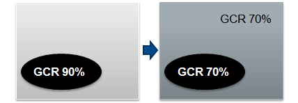
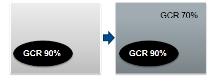
In GCR (Gray Component Replacement), conversion from the Device Link is by default to the target GCR values. In PDF documents that already have elements with a higher GCR value or have user-defined elements with a high amount of K, this can result in a reduction of the calculated K percent compared to the initial value. If you enable "Keep GCR", the GCR values and consequently the percentage of K are preserved for these elements. The total dot area of the output profile is preserved (normally, logos or the like are elements with a high GCR and are to remain unchanged).
Standard process:
"Keep GCR" enabled:
This option applies only to RGB input profiles. It makes sure that pure black text from RGB (R=G=B=0) is converted automatically to 100% K in the CMYK profile.
Profile description
The profile description is generated automatically from the names of the source and target profile and the profile parameters. This entry is suggested as the file name of the ICC target profile when it is being saved.
Use this name or type any description for the ICC target profile into this box. We recommend that your description shows you at once what type of profile it is.

Note: If you use a DeviceLink profile as a source profile in MetaDimension or Prepress Manager, any existing target profile will be ignored. For that reason, we recommend that you assign a name that contains a reference to a link profile.
Calculate DeviceLink profile
RGB is calculated to CMYK or CMYK to CMYK when you create DeviceLink profiles.
Click "Calculate" to link both selected ICC profiles and calculate the DeviceLink profile.
An appropriate message appears if calculation is successful.
Save profile
Click "Save" to open the "Save file" dialog.
The start folder for ICC profiles set in "Preferences" displays showing all items. By default, the file name box displays the profile description. "ICC profile (.icc)" is selected as the file type.
If needed, you can change these settings.
Click "Save" (in the "Save file" dialog) to save the DeviceLlink profile.
After calculation of the profile is finished, close the dialog box by clicking "OK".

Note: DeviceLink profiles are not supported by all applications. But many workflow applications and RIPs support Device Link profiles.
For more information, refer to the booklet "Prinect – Color and Quality: DeviceLink Profiles" (see PDF files "Basics").