Create a Digital Press at the Cockpit
Like an offset sheetfed press, the digital press is also created using the Central Device Manager (CDM). In this way, you can plan digital printing operations at the Scheduler and are given feedback in Analyze Point.
The General Settings are identical when setting up a digital press.
1.To do this, go to "Administration > Settings > System" and select the computer name of the Prinect server.
2.Select "Add device" in the context-sensitive menu of the CDM.
The "Device assistant" opens.
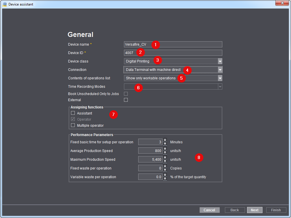
Device assistant - General settings
Device name
Under "Device name" (1), enter the designation for the digital press you wish to connect. The designation of the workplace/machine in the Prinect workflow must be unique. You may use no more than 30 characters. This designation serves as the press identification for the users in the entire Prinect workflow (in the scheduler and in Analyze Point, for example).
Device ID
Enter a device ID (2).
•The "DeviceID" must contain only the characters [a-z], [A-Z], [0-9].
•The device ID serves for unique assignment of the machine in your Prinect workflow. The device ID must be matched with the Management Information System (such as Prinect Business Manager).
•In the Digital Printing Terminal, the device is given the name entered as the device ID in this box.
Point to note on a Linoprint L ITS600
By default, ITS600 is filed as the device ID on a Linoprint L ITS600. "ITS600" must be entered in exactly the same notation as the device ID if you did not change the standard device ID on the machine.
Device class
Select the "Digital Printing" entry (3).
Select the connection type (4).
"Data Terminal with machine direct"

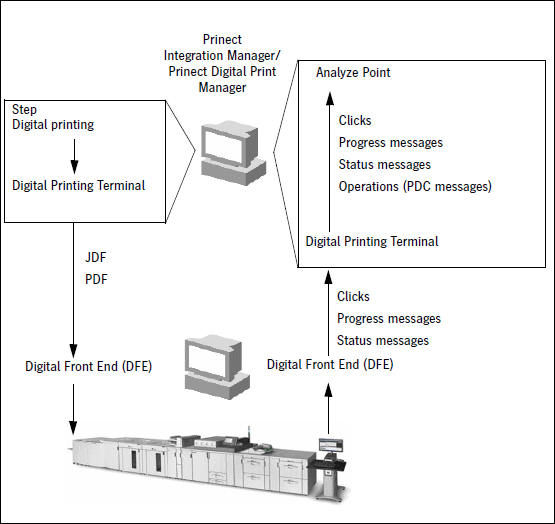
This connection type offers optimum integration into the workflow. In this context, the "Digital Printing" step first submits the jobs to the "Digital Printing Terminal". Here, you can change the order of the jobs and inspect the job data (see Digital Printing Terminal ).
The Digital Printing Terminal submits the jobs to the digital front end (DFE) where they are rendered and finally submitted to the digital press.
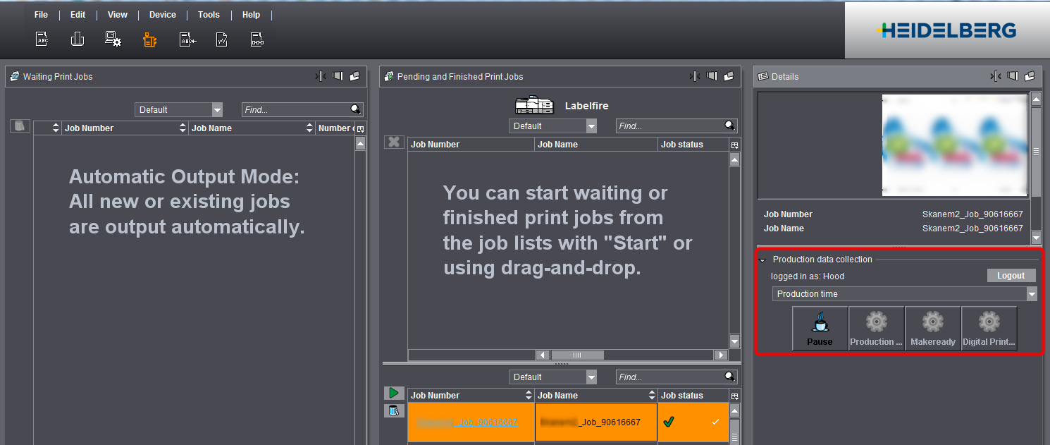
The press reports back various messages like clicks and progress messages to Analyze Point. PDC messages can also be recorded using the Digital Printing Terminal (see screenshot).

Press feedback is displayed in Analyze Point (see Feedback to Analyze Point).
"Direct connection of the machine"
In contrast to "Data Terminal with machine direct", the print jobs sent from the "Digital Printing" step are run through the Digital Printing Terminal and printed directly on the press. On the Digital Printing Terminal, you can only abort the jobs and pause them depending on the device type. You can neither change the order in the print queue nor collect production data. Messages like clicks and progress data are fed back and displayed in Analyze Point in case of the "Data Terminal with machine direct" connection type.
Choose this connection type for Linoprint L ITS600. This is necessary because administration of the print jobs runs directly on the machine and not on the Digital Printing Terminal.
In this workflow, a pure production data collection runs using a Data Terminal. The Data Terminal is located on a separate PC and must not be mixed up with the production data collection via the Digital Printing Terminal. No job data are sent to the digital press and the machine does not report any messages to the Prinect Integration Manager/Prinect Digital Print Manager. This connection type is only relevant if you want to collect production data in your Management Information System and/or in Analyze Point.
Contents of operations list
Select the item you want in the list box (5). You can find a detailed description of the effects of the selection in Contents of operations list.
Time Recording Modes
Select the item you want in the list box (6). This function is available only for a Data Terminal connection.
You can find a detailed description in the Time Recording Modes.
Assigning functions
You define the roles for production data collection here (7). This means you define who can log in to the machine. You can select this option only with connection types "Data Terminal with machine direct" and "Data Terminal". You can find a detailed description of the roles in Assigning functions.
Performance Parameters
You do not need to change anything in the "Performance parameters" section (8). Defaults from the Master Data Store are entered in these boxes. The standard values entered here are only used as a template for calculating production times in a newly created operation. The calculated production times are then taken into account when scheduling the operation in the scheduler. In a Prinect workflow with a Management Information System (MIS), the production time are provided by MIS.
The "Performance parameters" are also important for the Planning Assistant. If no MIS data are available, these values are used to calculate how long an operation will take. For details about the Planning Assistant see Planning Assistant.
Click "Next". Your next step is to select the machine type and connect to the press.
Device Assistant - Machine Type Selection
Specify the parameters of your digital press in this window. There are different settings that depend on the press model.
Setting up press model parameters for Labelfire, Primefire and Linoprint L
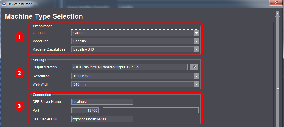
Press model (1)
For Labelfire, choose "Gallus" as Vendor, for Primefire "Heidelberg", and for Linoprint L "Linoprint L". Model line and Machine Capabilities are set automatically.
Settings (2)
This is where you enter the folder to which the TIFF or BMP files will be written for the digital press. The press must be able to access this folder later. In other words, the folder has to be shared in the network, and there has to be a user having at least read and write permissions.
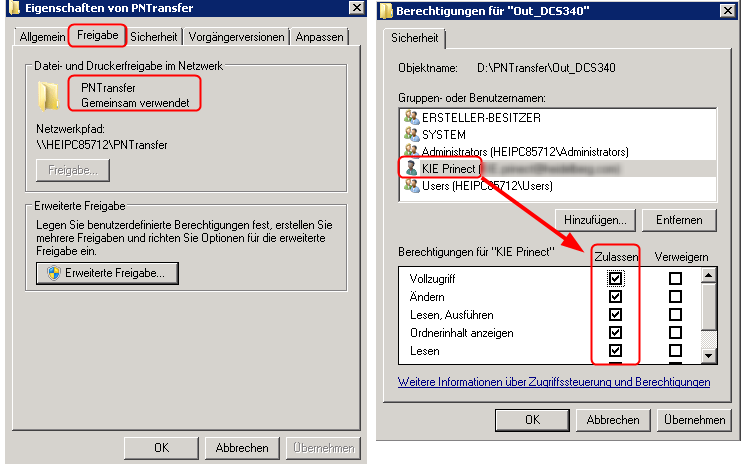
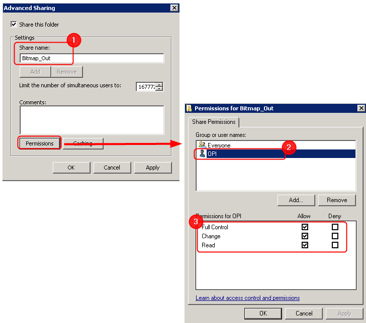
Special parameters for Linoprint L
The folder must be enabled with "Bitmap_Out" as the name (1) so that the Linoprint L can read the files in the output directory. The "OPI" user (2) must have the permissions to access this folder (3). The "OPI" user must have been set up beforehand on the computer.

•"Output format" list box (2)
This is where you select the output format, depending on your machine. On a Linoprint L ITS600, this depends on the electronics. You must select DSP2-BMP for machines with DSP2 electronics. You must select DSP3-TIFF4 for machines with DSP3 electronics.
•"Resolution" list box (3)
This is where you select the resolution, depending on your machine.
•"Web width" list box (4)
This is where you select the web width, depending on your machine.
Connection (3)
Enter the server of the digital front end in "DFE Server Name" (Digital Front End). You can enter either the IP address or the name of the server.
The "Port" is entered automatically. You have to edit it only if you have changed it on the DFE server.
In "DFE Server URL", the URL is made up of the server name and the port. You do not need to make any changes in this box.
Setting up machine model parameters for Versafire CV/Linoprint CV, Versafire CP/Linoprint CP and Linoprint C
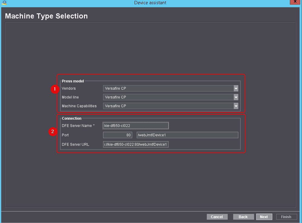
Press model (1)
Depending on the machine model, choose "Versafire CV", "Versafire CP" or "Linoprint L". Linoprint CV/CP was renamed to Versafire CV/CP; for this reason, the Linoprint CV/CP entries will remain for all presses set up until Prinect 2017. Choose Versafire CV/CP if you are setting up a new press. The functions of the machine models are identical.
Setting up machine capabilities for Linoprint C
•C751
You can choose from the following default finishing devices for Linoprint C751:
|
Machine Capability |
Explanation |
|---|---|
|
Fold_Staple_Interposer_SR5040_Trim_Punch4 |
Multi folder, high capacity stacker, booklet finisher SR5040 with Cover Interposer, front trimmer and 4 hole punching |
|
Fold_Staple_SR5030_Punch4 |
Multi folder FD5010, high capacity stacker SK5020, standard finisher SR5030 with 4 hole punching |
|
Interposer_SR5040_Trim_Punch4 |
Booklet finisher SR5040 with Cover Interposer, front trimmer and 4 hole punching |
|
SR5030_Punch4_Plockmatic |
Standard finisher SR5030 with 4 hole punching, Plockmatic |
|
Staple |
High capacity stacker SK5020 |
•C901
You can choose from the following default finishing devices for Linoprint C901:
|
Machine Capability |
Explanation |
|---|---|
|
SR5000_Punch4_Interposer_Plockmatic |
Standard finisher SR5000 with 4 hole punching and Cover Interposer, fully automatic Plockmatic (with page trimmer) |
|
SR5020_Punch4_Interposer_2Staple |
Booklet finisher SR5020 with 4 hole punching and Cover Interposer, two high capacity stackers |
Enter the server of the digital front end in "DFE Server Name" (Digital Front End). You can enter either the IP address or the name of the server.
The "Port" is entered automatically. You have to edit it only if you have changed it on the DFE server.
Setting up the machine model parameters for Canon, HP Indigo, Kodak NexPress, Konica Minolta, Ricoh, and Xerox
Machine model
Choose the respective manufacturer, the model line and the machine capabilities.
Connection
See Connection (2).
Setting up machine model parameters for unsupported digital presses (Generic)
All digital presses not yet supported by Heidelberg (see ) can be connected via a generic interface. For such machines, the "Generic" item is available in the machine model list box.
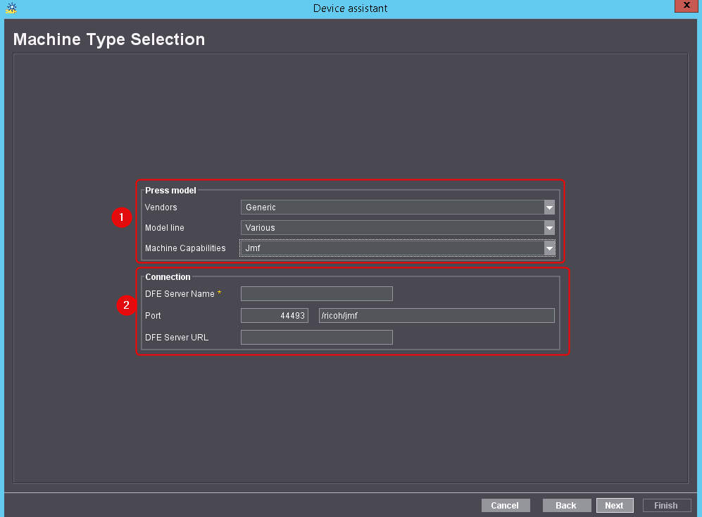
Press model (1)
Select "Generic" as the Vendor. The model line is set automatically. The items "Jmf" and "Hotfolder" are available as machine capabilities.
•Jmf
The Jmf connection is used to control -third-party DFEs that feature a Heidelberg interface. This also means that the press cannot retrieve any information about printing material, for example. To connect a machine via Jmf, the DFE must feature the Heidelberg interface. Please contact your vendor to find out if your machine has this interface.
•Hotfolder
You can connect the machine via a "Hotfolder" if the DFE does not feature a Heidelberg interface. The Prinect System will write the PDF files for the digital press into a specified folder later. This connection type does not allow any feedback from the digital press. This also means that the press cannot retrieve any printing material. Instead, a default group of printing materials is created automatically after you have set up the press. You can edit this group later. See Printing Materials.
Output directory
Specify the folder (hotfolder) here to which Prinect Digital Print Manager is to write the PDF files for the digital press later. This folder must be shared.
The output directory is a root directory. In the Prinect workflow, all subdirectories of this directory are treated like "virtual printers" (see Printing Materials). As a rule, the names of the subdirectories you set up there should match the names of the "virtual printers" you set up on the DFE.
Connection (2)
See Connection (2).
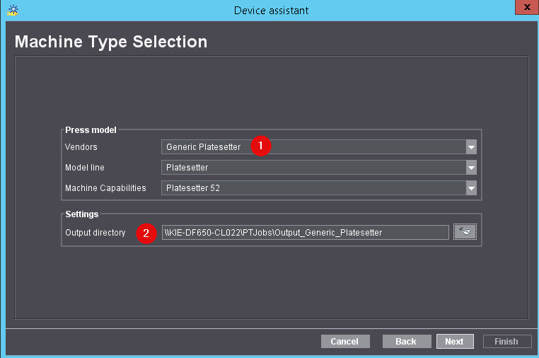
Setting up a CTP device for PDF output for small-format platesetters (Generic Platesetter)
Small print shops often have a simple small-format offset workflow in addition to their digital printing workflow. These print shops produce comparably simple products and use simple tools for press sheet generation. In this context, outputting a layout as PDF to the platesetter's RIP is often sufficient.
For this purpose, Heidelberg offers an option to create a layout in the Digital Print Manager and to output it as a PDF. The format is restricted to a maximum size of 656 mm (width) x 530 mm (height).
To output such a PDF, a digital press of machine model "Generic Platesetter" (1) has to be set up at the CDM. A network folder the RIP can access must be specified as Output Directory (2).
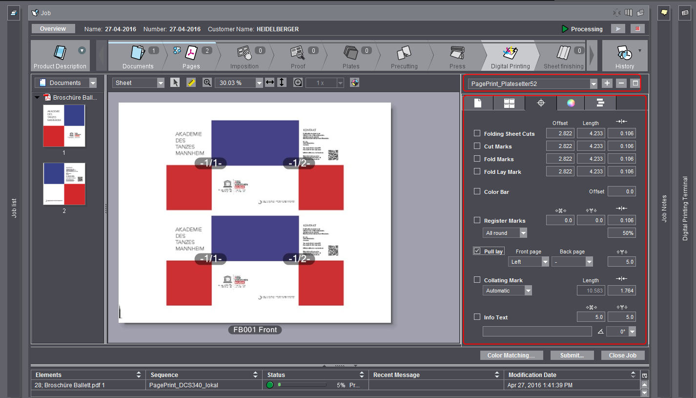
You can then set up a "PagePrint" sequence selectable in the "Digital Printing" step for the new device. Here you can edit the plate format, specify the position of the sheet and place pull lays.
Further Device assistant steps for Data Terminal devices
For digital presses of connection types "Data Terminal with machine direct" and "Data Terminal", the Device assistant offers steps for setting up production data collection parameters. These settings are identical to those of other Data Terminal devices. In a direct connection without Data Terminal you go directly to the Device Assistant - Summary window.
For Data Terminal steps, see:
•Device Assistant - "Assigning operation groups" and "Assigning operations"
•Device Assistant - Assigning User Groups