
"Print marks settings" tab for Labelfire 340 presses
Note: The print mark settings differ, depending on the press that the PagePrint sequence is set up for. See also:
·"Print mark settings" tab for toner-based digital presses (Heidelberg Versafire) and CTP devices and
·"Print marks settings" tab for Primefire 106 presses.
The available marks options are matched to the Labelfire 340 press. This means that only "PQC Strip", "Punch Mark", "Sensotec Mark", "Register Mark" and "Info Text" types of marks are offered for selection.
"PQC Strip" mark type
PQC (Print Quality Control) strips are special quality control marks that are required for label printing. The height of the strip (in mm) is measured from the top margin of the web.
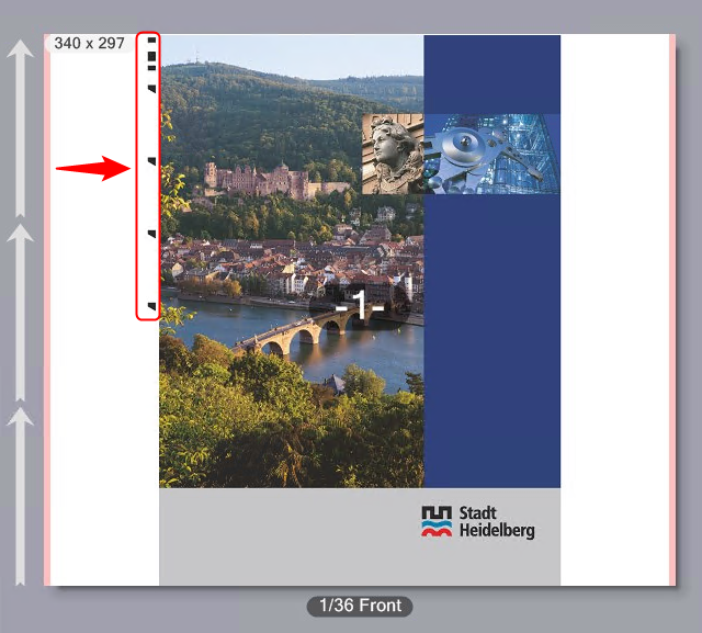
"Punch Mark" mark type
A special mark is needed for punch synchronization in the Labelfire 340 press. It is a box whose height, width and position can be set. By default, this mark is a square with an edge length of 1 cm at the position [0.0] (top left corner).
Use the "X" and "Y" values to set the offset of the punch marks to the subject in horizontal and vertical direction.
You define the size of the punch marks with "Height" and "Width".

Note: Sensotec marks and punch marks are always output in 100% black on the Labelfire, in other words, without color management.
"Sensotec Mark" mark type
Sensotec marks are special marks that are used for automatic register control.
Use the "X" and "Y" values to set the offset of the Sensotec marks to the subject in horizontal and vertical direction.

Note: Sensotec marks and punch marks are always output in 100% black on the Labelfire, in other words, without color management.
Digital printing unit is Master / Slave
If a print job has other colors to be output in addition to digital printing, for example, also in flexographic printing, it is important to set whether digital printing will be done first or after flexographic printing. A great amount of waste can be the result if the start code is also printed only with digital printing but the flexographic colors are printed first.
Printing is always in the order in which the printing units are set up. The following is valid for the Master/Slave setting:
•If you select "Master", the start code is output by digital printing. If the flexographic printing units come before digital printing, the flexographic colors are printed first (although they are the "Slave"), followed by digital printing.
•If you select "Slave", the start code is output by the first (flexographic) color to be printed. The digital printing unit is "Slave" and then outputs the last mark.
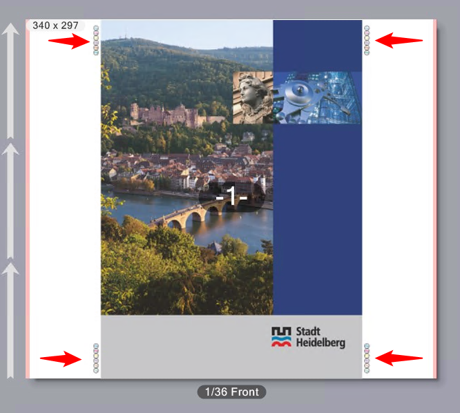
Register marks and spot color patches
This is where you can set that register marks and spot color patches will be printed.
Spot color patches are control strips made up of patches filled with spot colors. This makes it possible for spot colors to be measured on the substrate.
The register marks for Labelfire presses are designed so that a color depicted as a cross on a black bounding circle is corrected. The marks are placed on the side of the subject, either one at the top left and one at the bottom right or two marks each on the left and right.
Position
Use the "X" and "Y" values to set the offset of the register marks and/or the spot color strips to the subjects in horizontal and vertical direction. The position refers to the folding sheet.
In the "Marks per Side" box, you set the number of register marks on the left and on the right of the substrate. A maximum of two register marks per side can be output. In the example, two marks per side are enabled.
In the "Marks per Side" box, you set the number of register marks on the left and on the right of the substrate. In the example, two marks per side are enabled.
Spot Color Patches
When you enable this option, control strips made up of spot color patches are printed. You can print spot color strips together with register marks or on their own. You can set the offset of the spot color strip to the register marks if register marks and spot color patches are both enabled. This is the offset of the lower edge of the spot color strip to the top edge of the lower right register mark. In other words, the spot color strip lies above the lower right register mark.
Register marks and spot color strips are placed one below the other in a straight line. The size of a color patch is 6mm by 6mm.
Labeling
If wanted, you can enable labeling of the marks.
"Info Text" mark type
You can use this option to define special text marks by entering the appropriate text in the edit box. For example, you can enter information on specific output options, or comments on finishing.
In the "X" and "Y" boxes define the position of the mark, starting from the reference point in the bottom left corner of the subject.
You define the orientation of the mark in the angle list box. The angles of rotation are measured in the clockwise direction. A rotation angle of 90° produces text running vertically upwards, that is read from top to bottom. A rotation angle of 270° produces text running vertically upwards, that is read from bottom to top.
Example 1 in the diagram below displays info text in the horizontal direction, example 2 shows it in the vertical direction.
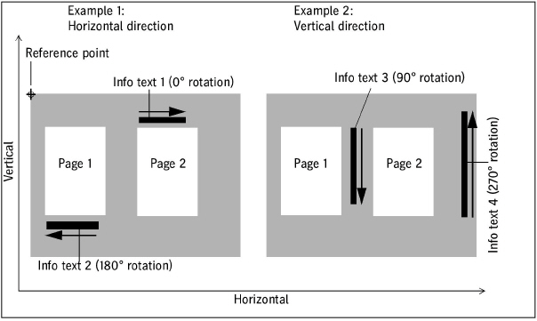

Note: The angle for info text marks is set by default to 90° for Labelfire presses. This is to avoid the info text mark from inadvertently running across the 1up.
Color Settings for Digital Printing
You set up color management for digital printing in the "Color settings" tab. Because these settings vary according to the type of digital press used, the parameters will be described separately:
•"Color settings" tab for toner-based digital presses (Heidelberg Versafire EP, EV, CP, CV)
•"Color settings" tab for Primefire 106 presses
•"Color settings" tab for Labelfire 340 presses
•"Color settings" tab for CTP devices driven as a "Digital Platesetter"

Note: You can invoke an introductory documentation to color management taking into account color management in the Prinect Digital Front End by clicking:
Prinect Color Management - User's Guide
General information about color management:
The goal of Color Management is to standardize the color reproduction of digital image data throughout the entire editing process. Color space conversion was introduced to achieve a standardized color representation. Color space conversion basically matches the image or graphic data from the creator color space (e.g. color space of a digital camera) to the color space of the output device or process (e.g. color space of a press or color printer).
The diagram below shows the basic principle of a color space conversion:
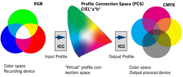
It must be remembered that the color space of the recording device and the color space of the output process are device-dependent. In other words, these color spaces describe the color-specific properties of the recording device (digital camera, scanner, etc.) and of the print process used (press, CTP device, color proofer, monitor). To establish a standardized color management process that can handle different input devices and various output channels, a universal, device-independent profile connection space that links the input profile with the output profile is often interposed. The color spaces themselves cannot be influenced by color management because they are determined either by the physical properties of the devices concerned or, in the case of the profile connection space, defined as universal.
•First of all, the data are in the color space of the input device (scanner, digital camera, etc.) (device-dependent color space).
•The data are converted to the device-independent profile connection space (CIEL*a*b* color space) when the input ICC profile is enabled. The input ICC profile is selected and configured in the "Enable CMYK Color Management" option or in the case of RGB objects is taken from the PDF documents.
•For the output, an output ICC profile suitable for the printing press or the output process is activated. This profile adjusts the image data to the color space of the output device. As a result of this, the image data are again device-specific. The output profile is selected in Output Profile.
The ICC profiles can be present in different ways for the color space conversion:
•Embedded ICC profiles: The ICC profiles are contained in the document file and are used during the respective transformation steps.
•ICC profiles that are not embedded: The ICC profiles must be available as separate files on the Prinect server and/or in "Administration > Resources > ICC Profiles" (see also ICC Profiles). They are selected in the Color Management settings and then used for conversion.

Note: Details about Color Management in the Prinect Manager can be found in: "Color Conversion" Option.
Machine setup using output conditions
The basic settings for color handling and finishing are filed in "Output Conditions" for the Primefire 106 and Labelfire 340 inkjet digital presses Output conditions are files containing the appropriate output parameters. Output conditions are created and saved using the Prinect Color Center. To be able to use the output conditions, the related files must be filed on the Prinect server and must be accessible from the Cockpit.
Because the output conditions also contain the finishing parameters, there is no "Print and finishing settings" tab for these machines.
More details about creating output conditions can be found in the Online Help of the Prinect Color Center.