Setup of digital presses with a Digital Print Connector
If you have devices with a "Digital Print Connector" connection, the setup for finishing is basically just the selection of a predefined output configuration of the press and finisher, e.g. "HP Indigo 3500". Output configurations are defined through "virtual printers". They are set up at the operator workstation ("digital front end") of the press and stored there.
You can select the output configuration you want in the "Virtual Printers" list box. This configuration displays as a symbol matching your selection.
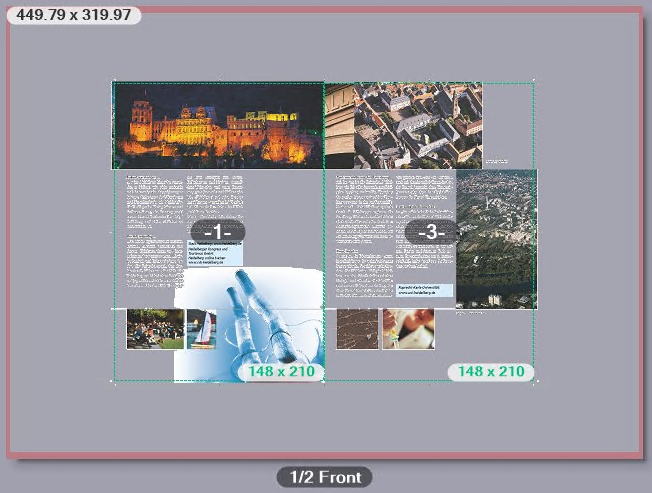
The center of the "Digital Printing" window shows a preview of the the imposed sheet layout.
Note: In the Pages Lists or Documents view, you can open single pages in Acrobat with a double click.

Note: The grain direction of web material in the press is indicated by arrows in the preview whenever web material is used as the substrate.
Display of sheet data in the preview
In the preview, you can view different details about the sheet currently shown:
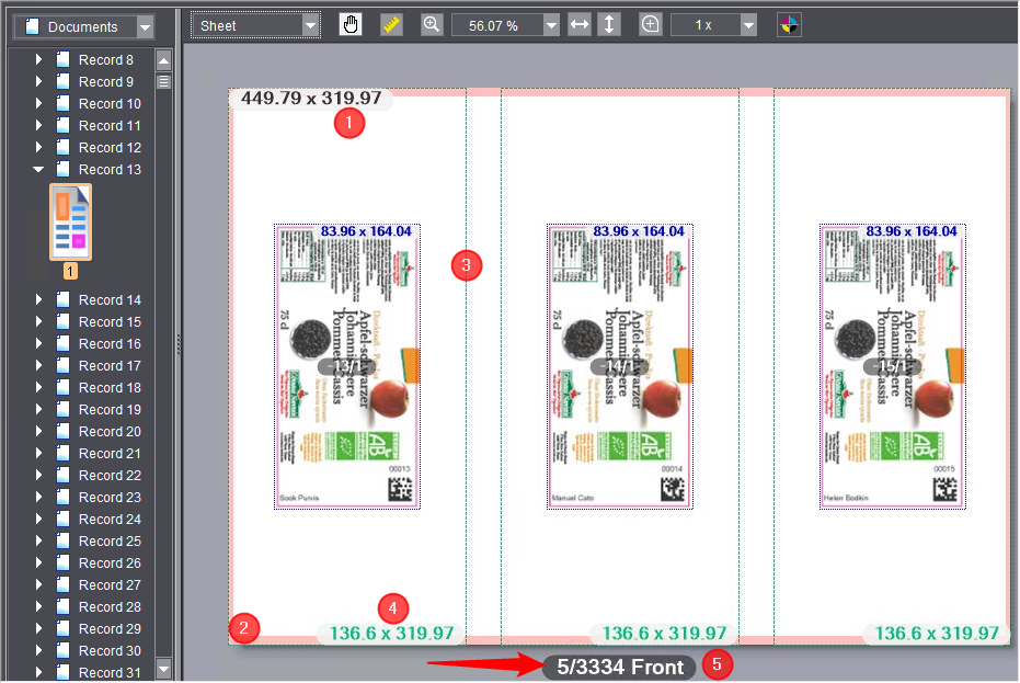
•The sheet dimensions (1) display at the top left corner of the sheet.
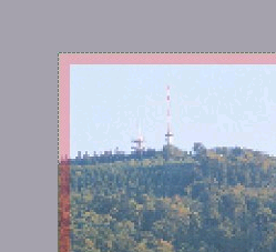
•The non-printable border (2) is highlighted in pink.
•The bleed and trim allowance (3) display as broken lines.
•The dimensions of the trim box (4) display in the bottom right corner of the trim box.
•The sheet label (5) contains the following data:
·Sheet number
·The total number of sheets in the job.
In many cases, e.g. when processing PDF/VT documents with many data records, it is important to know how many sheets will be produced in total for a job. The sheet quantity is automatically recalculated and the display refreshed if you modified in the layout settings, for example, the number of columns or rows of pages/subjects on the sheet.
·Information about whether it is the front or back.
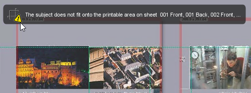
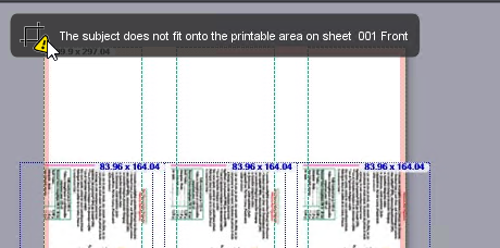
•A warning displays in the top left corner of the sheet if there are issues about the definition or the data on the sheet. A tooltip provides you with more details about this.

Above the pages there is a "toolbar", containing the following elements:

|
|
This is where you can select how the sheet layout will display. |
|
|
You can use this tool to move the image content of the preview. |
|
|
Use this tool to perform linear measurements in the sheet layout. The dimension line runs only horizontally or vertically if you hold down the Shift key while you are dragging the dimension line. |
|
|
Use this tool to set the display scale of the preview. |
|
|
Match view to page width or page height. Use these buttons to resize the view of the pages so that the width or height of the selected pages exactly matches the display window (equivalent to "Fit Width" or "Fit Height" in the context-sensitive menu). |
|
|
Use this tool to zoom in on a section of an image like a magnifying glass. |
|
|
This tool provides you with details about the object indicated by the mouse pointer. |
You can select between the following view formats in this list:
•Sheet
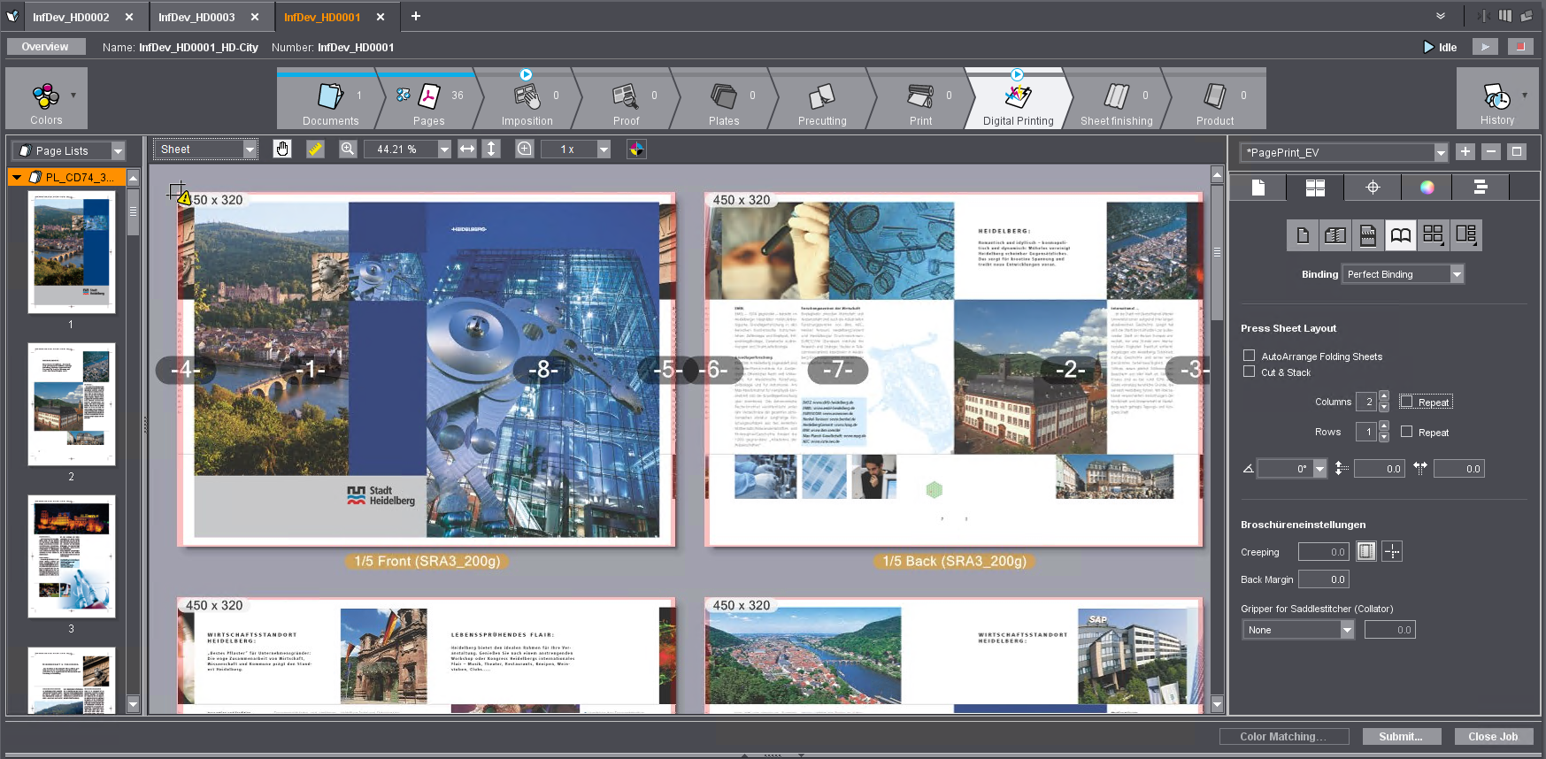
In this view, the printed sheet and – if assigned - –the original page content is depicted. The imposition page number (not the page number defined in the PDF) of each document page is shown in white letters on a gray box above each page, in order to be able to check the page layout on the sheet. If the pages contain images, these are displayed in full color (all color separations). In this view you get an advance view of the print result and you can apply the dimension, magnifying glass and information tools on the separate page areas. When changing the sheet configuration or the magnification scale, the view is recalculated, so it may take some time until the view is fully represented.
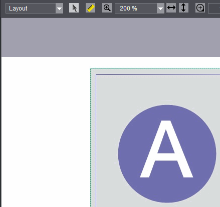
•Layout
This view provides a quick view of the sheet layout, without the page content being shown. The pages are only displayed as gray areas which differ in color from the underlying surface of the substrate. The page numbers are displayed in gray boxes. The direction of rotation of the pages is displayed in each case with a letter "A".
You can use this view to quickly view the page and sheet parameters and to correct them where necessary. Unlike the sheet view, there are no significant computation times when calculating the view.
•Separations
In this view, all the color separations defined in the pages are displayed as adjacent sheets. If, for example, the four process colors are defined in a print job, the separations display in the order in which they were printed on the press. If the set magnification does not allow the simultaneous display of all color separations, a horizontal scroll bar is shown that you can use to switch to the corresponding color separations.
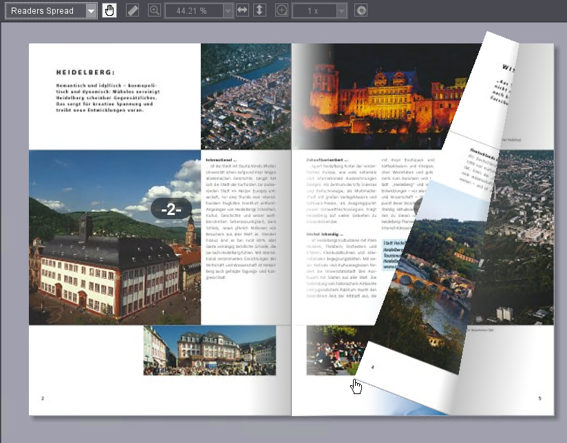
•Reader's Spread

Prerequisite: Readers Spread is not available for single page layouts.
In this view, you can look at the document pages as a "virtual booklet" on the screen. The document pages display in a 2-page layout, like an open booklet. Clicking and dragging while holding down the left mouse button on the left and/or right outer edge of the brochure scrolls forwards or backwards through the brochure. None of the tools of the preview area are available in this view.
|
|
You can use this tool to move the visible image content with the mouse if a zoom factor is set that allows only a partial view of the sheet. Once you position the mouse cursor over the preview and press the left mouse button, the mouse cursor changes into an outstretched hand and you can move the image content while holding down the mouse button. |
|
|
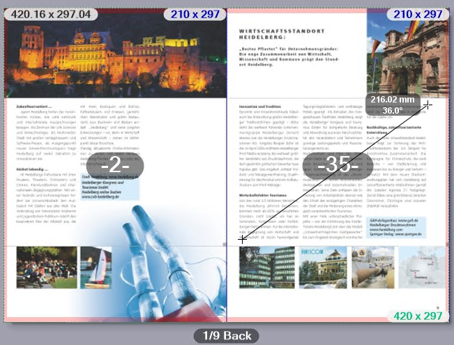
You can use this tool to measure lengths and angles in the preview area in the "Sheet", "Layout" and "Separations" views. The Dimension Tool is used as follows: |
1.Click the Dimensions icon to enable the tool.
2.Left-click the starting point of the measuring section and hold down the mouse button.
3.Drag the mouse cursor to the end of the measuring section. The length of the distance and the angle relative to the horizontal are displayed in a box next to the mouse cursor. If the angle from the horizontal (x-axis) is measured counterclockwise (upper semicircle), it is counted positively (up to 180°). If the angle is measured clockwise (lower semicircle), it is counted negatively (-180°).
If you hold the Shift key while dragging the measuring line, the possible directions are limited to 90° angles. In this way you can accurately measure horizontal or vertical distances.

|
|
You can use the zoom tool to set the display scale for the "Sheet", "Layout", "Separations" and "Color Coverage" views. You can do this in two ways: |
•Per click: To do this, select the Zoom tool icon and click anywhere in the preview area. Each click doubles the zoom factor, in other words a zoom factor of 33% is increased to 66%. Pressing and holding the Alt key and simultaneously clicking reduces the zoom factor by half. Instead of the plus sign in the mouse cursor, a minus sign is displayed.
•By selecting from the list of zoom factors: You can also select zoom factors in the list box next to the Zoom tool and adjust the magnification directly.
If the list of zoom factors does not open, the currently set zoom factor is displayed directly.
|
|
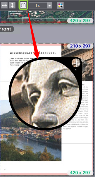
If you want to examine some details of the illustrated pages more closely, you can use the magnifying glass in the "Sheet", "Layout", "Separations" and "Color Coverage" views. |
1.First, select the desired magnification scale in the list box next to the magnifying glass icon. The largest scale is "1 x", the smallest is "1/16 x".
2.Select the magnifying glass tool and hold the left mouse button pressed over the point that you want to examine. A magnifying glass window is displayed. The center of the crosshairs in the small circle indicates the center of the magnified area. The detail in the selected magnification scale is displayed in the large circle.

|
|
You can use the Info tool to get detailed information about the individual objects on the pages in the "Sheet", "Layout" and "Separations" views. |
1.Enable the Info tool.
2.Click on the object (image, text object) in the preview area for which you want to get information, and hold the left mouse button down. The object is displayed semi-transparent and an information window is displayed over the top.

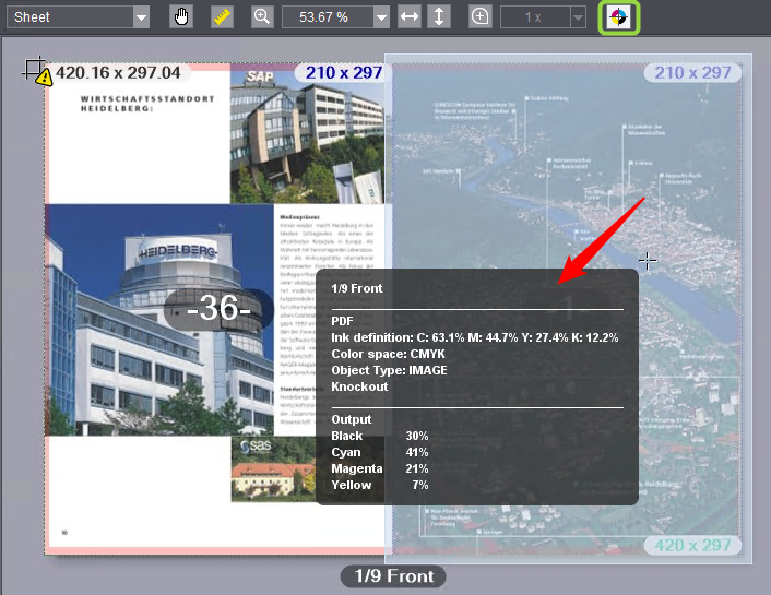
The window is divided into three sections and shows the following information:
|
Top Part |
Sheet name, front or back of the sheet |
|
Middle Part |
Information from the PDF file (original): •Ink definition (color separations and their percentages, also spot colors if any) •Color space •Object type (image, text, etc.) •Embedded color profile (if any) •Knockout/overprint information |
|
Bottom Part |
Color data as used for printing (as per output settings): •Color separations and their percentages (also spot colors if any) |
3.Leave the mouse position as it is and click repeatedly with the left mouse button: the object changes with each click and the values are refreshed accordingly in the bottom part. The object currently active is highlighted in the preview. This lets you measure the values of other objects on the page fast and, if necessary, measure and compare the values of overprinting objects separately.
The context menu in the preview area
If you open the context menu by right-clicking over the layout view in the preview area, you are presented with the following options:
|
Fit the width |
You set the magnification scale so that the entire width of a press sheet or two press sheets side by side (front and back), depending on the layout type set (single-sided or double-sided layout), display across the full window. •On a single-sided layout (front only), the width of a sheet always displays, using the full width of the preview. •On a double-sided layout, the front and back sides display side by side, using the full width of the preview. |
|
Fit Height |
You set the magnification scale so that the entire height of a press sheet displays, filling the whole window. •On a single-sided layout (front only), the height of a sheet always displays, using the full height of the preview. •On a double-sided layout, the front and back sides display side by side, using the full height of the preview. |
|
Previous view |
The view (zoom factor) preceding the last view change is restored. |
|
Show —> Page Numbers |
This command lets you show or hide Cockpit-specific page numbers.
|
|
Show > Boxes/Dimensioning |
This command lets you show or hide the page boxes (see "Bleed" and "Trim Allowance" group). The bleed boxes are shown in green and the trim boxes in blue.
|
|
Show > Non-Printing Margin |
This command enables the view of a non-printing margin if one is set (see "Non-Printing Margin" option). The non-printing margin is indicated by a transparent, red border.
|
|
Show > Warnings |
You can show or hide warnings with this menu item.
|
|
Show > Transparent Background |
You switch the background to "transparent" with this menu item. This means that the printing material or page background is hidden, allowing the background of the preview window to shine through. This function lets you, for example, visualize printed areas on a transparent printing material.
|
|
Add PDF Mark |
This command lets you add marks available as PDF files to the sheet. The context-sensitive menu must open directly over the place on the sheet where you will insert the mark. The "PDF Mark Properties" dialog opens (see "PDF Mark Properties" dialog). |
|
Remove |
This menu item is available only if the mouse pointer hovers over an added PDF mark. The PDF mark is removed. |
|
Properties |
This menu item is available only if the mouse pointer hovers over an added PDF mark. The "PDF Mark Properties" dialog opens (see "PDF Mark Properties" dialog). |
|
Color measuring |
This menu command is available only if the mouse pointer is located over a text or graphic object that is defined in a spot color. This command lets you assign a different spot color to the object by measuring a template with a colorimeter. The "Color measuring" dialog opens for this (see "Color measuring" dialog). |
|
Assign Alternate Color |
This menu command is available only if the mouse pointer is located over a text or graphic object (and not over an image) that is defined in a process color (RGB, CMYK, etc.). This command lets you assign a spot color in the job to the object, import a spot color from a spot color table (see "Import Colors" dialog) or define a new spot color. The "New Color" dialog opens for this (see "New Color" dialog). In this dialog, you can also use the "Color measuring" button to determine a spot color by measuring it with a colorimeter (see "Color measuring" dialog). |
|
Assign Paper |
Use this command to assign a different paper to the one set to the page on top of which you displayed the context-sensitive menu. Only papers that are available in the system configuration and that have the same format as the previous paper display for selection. For example, you cannot assign an A4 paper to an A3 page. |
|
Separations |
In the "Sheet" display mode, you can enable or disable single separations separately for each sheet for viewing them in the Cockpit. In this process, the shares of the disabled separations are subtracted out of the color displayed; the preview shows only the enabled color separations of a sheet. By default, all the separations are enabled. |
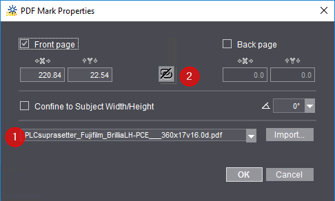
In the list box (1), you can select a PDF marks file already known in the system. Use "Import" to select and import a PDF marks file in the file system of the Prinect server. We recommend that you file PDF marks files below the "PTConfig" or "PTJobs" folder or the "PTDocs" folder of the Prinect server and import it from there.
You can set on which surface the mark will be inserted using the "Front page" and "Back page" options.
The position of the mark displays in the "X" and "Y" boxes.
The mark is automatically inserted to the front and back when you click the position link button (2). Click again to remove the link.
You can set the orientation of the mark in steps of 90° in the angle list box.
"Confine to Subject Width/Height" option
Enable this option to make sure that the mark does not jut beyond the subject dimensions.
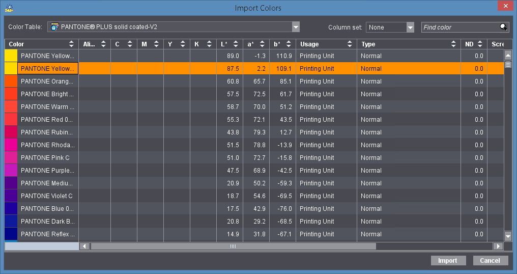
You can assign a spot color from one of the spot color tables available in the system to a process color (RGB, CMYK, etc.) using "Assign Alternate Color > Color Tables" in the context-sensitive menu.
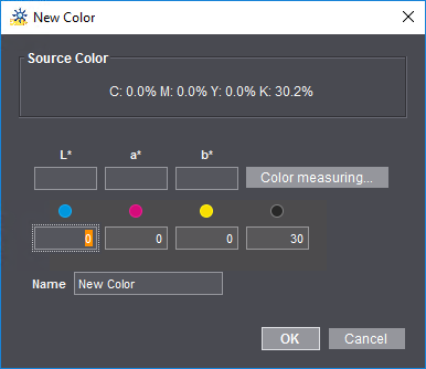
In this dialog, you can assign a new spot color to a text or graphic object that is in a process color.
The color channels of the object display in "Source Color".
The following options are available for defining a new spot color:
•You can type the color values (L*a*b* or CMYK) manually into the dialog or
•you can measure the color data with a connected colorimeter (only on Windows PCs). To do this, click the "Color measuring" button (see "Color measuring" dialog).
Then type in a name for the new spot color in "Name" and confirm with "OK".

Note: The color will be assigned only to the selected object.
In addition to entering color data manually, you can also add new colors by measuring a probe in the color table.

Prerequisite: At present, only the X-Rite EyeOne colorimeter is supported. Before you start measuring, the colorimeter must be connected to the Cockpit workstation on which you will measure the probe and it must be operational. A probe with the color you wish to measure must be at hand.
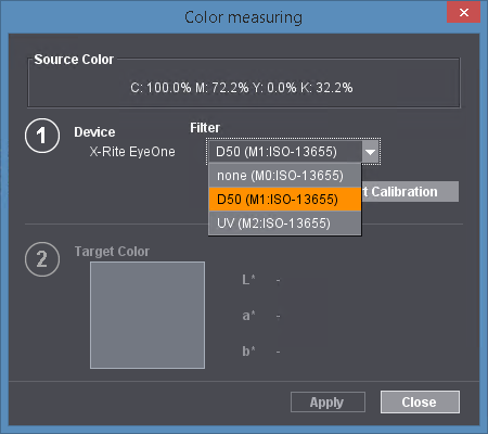
You can select one of the following filters with appropriate measuring modes in the "Filter" list box if you use Rev. E of the X-Rite Eye One:
•none (M0): this setting is the only option supported for older X-Rite Eye One versions.
•M1 (D50 standard illuminant): as of Rev. E.
•M2 (UV light): as of Rev. E.

Note: The filter must be set just before measurement. It is not possible to change the setting after measurement.
Proceed as follows to measure the probe:
1.Click "Start Calibration" to initialize the colorimeter.
An error message displays if the device is not connected or the driver not installed.
Area 2 of the dialog is dimmed during the close loop calibration of the colorimeter (lasts some seconds).
2.When close loop calibration is finished, you can position the sensor of the colorimeter on the item with the color you will measure. Now press the button on the left side of the colorimeter until the measured color displays in the "Target Color" box, showing its L*a*b* values.
3.Click "Apply". The L*a*b* values of the measured color are applied to the new or selected color item in the table and the "Color measuring" dialog closes.
Click "Cancel" to close the "Color measuring" dialog without making any changes to the color items.

Note: The settings that you make in this dialog are kept even after you, as the logged-in user, close the window and are available again when you reopen the "Color measuring" dialog later or from a different point in the Cockpit.

Prerequisite: This function for Primefire and Labelfire digital presses can be used only by Cockpit users who have the "Color Manipulation" permission. See "Permissions" Tab. This function is not restricted by this user permission for other digital presses.
Sometimes it is necessary to fine-tune color reproduction in digital printing just before printing, based on what you see on the screen. The "Color Matching" function lets you define such color settings based on a master page taken from the current print job. These settings only affect the print job that is currently being edited.

Note: The screen used should be calibrated for this functionality.
In the preview window, mark a page that contains one or more image objects that are suitable for evaluating color matching.
Click "Color Matching" on the bottom edge of the job window. The "Color Matching" dialog opens.
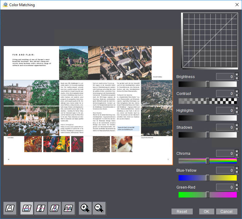
In this dialog, you can adjust gradation parameters "Brightness", "Contrast", "Highlights" and "Shadows". You can check these parameters in a gradation curve in addition to the preview.
Apart from these, you can also set color parameters "Chroma", "Blue-Yellow" weighting and "Green-Red" weighting. You can review these settings in the page preview.
You can set the gradation and color data either using the sliders or by entering values.
There are seven buttons in the lower left part of the "Color Matching" window:
•Use the five left buttons to switch the separating line between the original and the customized area of the image preview. You can choose between the following settings:
·No separating line (the whole preview window shows the customized color data)
·Horizontal separating line, the preview is split horizontally
·Horizontal separating line, the preview is duplicated
·Vertical separating line, the preview is split vertically
·Vertical separating line, the preview is duplicated
•You can use the two right buttons to scale up or down the preview.
The "Reset" button lets you reset all the settings to their original values. Click "OK" to apply the settings to the whole print job and close the "Color Matching" window.
Changes made to the color display are indicated by a green LED icon in the "Color Matching" button.
Submit print job to the printing press
When you have made and checked all the settings that are required for printing, you can send the print job to the digital press by submitting it to a "PagePrint" sequence.

Note: If you made changes to the setup of the "Digital Printing" step and want to use this setup for other print jobs, you should save all the output parameters that you made in this step as a new "PagePrint" sequence (see Save the setup of the step as a new template).
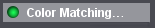
Click "Submit..." at the bottom right of the "Digital Printing" window to trigger the print process. The "Submit" dialog opens:
The header of this dialog shows you details about the number of pages and the names of the documents that are to be printed. Additional warnings may also appear. You can find more details about these warnings as a tooltip (1) or by clicking the message icon (2).
You can make the following settings in this dialog:
"Output" Group
This is where you can select between a normal print run and proofing.
Normal
This is where you can set the delivery quantity. The quantity depends on the type of product to be printed:
•If a product with multiple 1ups is output, such as two A4 pages on A3+ paper, the delivery quantity refers to each (multiple) occurrence of each page of the PDF document.
•If a product with single 1ups is output, such as a booklet, the delivery quantity refers to the number of copies output.
Test print

Prerequisite: This option is available only for toner-based Heidelberg digital presses, e.g. Heidelberg Versafire.
Enable this option if you wish to output the job as a test print to check the quality of the color, for example. Activation of this option has the following impacts:
•The delivery quantity is automatically set to "1" because usually you need only one copy as a test print. You can increase the delivery quantity manually, if required.
•The work type is set to "Internal".
•The parameters in the "Scheduling" section are disabled.
•After output, a test print is not tagged as "finished".
If the job is to be output normally after the test print, all you have to do is submit it again and disable "Test Print". The parameters set beforehand in the "Submit Elements" dialog are enabled again.
Proof

Prerequisite: This option is available only for inkjet-based Heidelberg digital presses, e.g. Heidelberg Primefire or Gallus Labelfire. In addition, "Inkjet Proof" must be enabled and set up in the active PagePrint sequence. See Separate Proofing for Heidelberg / Gallus Inkjet Digital Presses.
Enable this option if you wish to output the job as a proof to a connected proofer to check the quality of the color, for example. You can specify a delivery quantity separately for proofs. Activation of this option has the following impacts:
The delivery quantity is automatically set to "1" within the system because usually you need only one copy as a proof.
•The parameters in the "Scheduling" section are disabled.
•After output, a proof is not tagged as "finished".
If the job is to be output normally after the proof, all you have to do is submit it again and disable "Test Print". The parameters set beforehand in the "Submit Elements" dialog are enabled again.

Note: "File Output" can also be enabled in addition to "Inkjet Proof" in a PagePrint sequence for an inkjet digital press. Then the proof is filed as a soft proof, i.e. as a file in the file system of the Prinect server. See "File Output" Option.
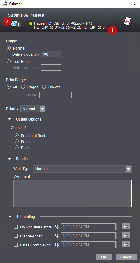
Output external separations or separations of "DieLine" proof colors

Prerequisite: This option is available only for inkjet-based Heidelberg digital presses, e.g. Gallus Labelfire or Heidelberg Primefire.
This option lets you save "external separations" as PDF files in the Prinect system environment. You can use this option, for example, to generate flexographic plates from the print job. Colors in the print job tagged by "Usage > External" in "Colors" are used as "external separations".
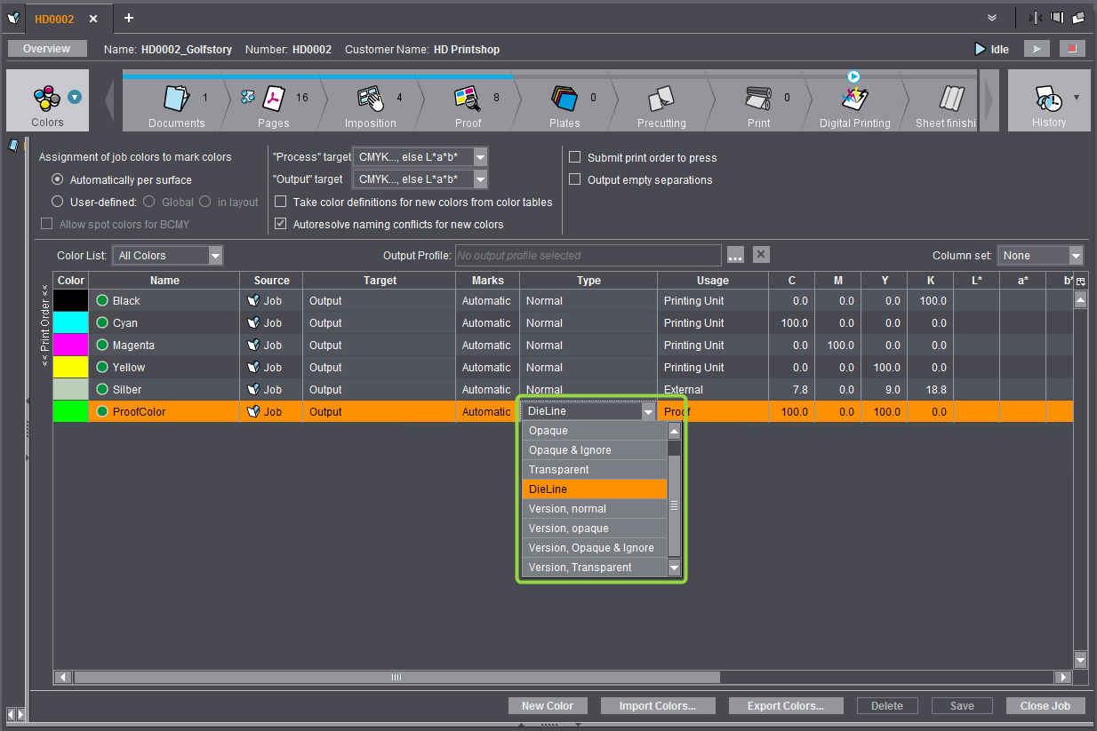
Likewise you can output separations with "DieLine" colors. "DieLine" colors are used frequently for proofing in sheet layouts, for example, to display the trim box or media box.
If external or DieLine colors are defined in the print job, you can use the browse button in "Output External Separations" in the "Submit" dialog to select a folder in the Prinect system environment where the separation PDF files will be stored (a PDF file is generated for each color separation). If necessary, you can also create a new folder.
"Print Range" group
This is where you can define whether you want to output all the pages or sheets or just a range of them.
In the "Priority" list box, you can set the priority with which the job will be processed in the Digital Printing Terminal or on the press.
"Output Options" group
In "Output Options" (this group can be expanded when needed), you can select whether only the front or the back or the front and the back will be output.

Note: Although Primefire digital presses can only print on one side, you can still select between front and back for outputs with an ImposedPrint sequence for Primefire as well. This gives you the option of printing surfaces defined as a back as a "front" on the printable side in the Primefire press.
In "Details" (this group can be expanded when needed), you can assign a work type. You only have to select a "work type" if the Prinect Manager is connected to an MIS (Management Information System) and work types are defined accordingly.
You can enter a comment about this print job in the "Comment" box. The comment is entered as a job note (see "Job Notes" View).
"Scheduling" Group
In "Scheduling" (this group can be expanded when needed), you can define a time range in which the print job is to be output. Clicking on one of the buttons to the right of the date boxes allows you to easily select the desired date from a calendar display.
Start printing
When you click "OK", the print job is submitted to the Digital Printing Terminal (see Digital Printing Terminal) or directly to the press or CTP device. If no other scheduling settings were enabled, the job is submitted immediately.