"Fix Assistant" See Fix Assistant
"Fix Tool Assistant" See "Fix Tool Wizard" Dialog
"Join Fix Tool" See "Rule Joint" dialog
"Auto Fix Tool" See "Auto Fix Tool" dialog
"Replace Gaps" See "Replace Gaps" dialog
"Fix 1up by Layout" See Fix 1up by Layout
There are the following modes for fixing 1up errors:
|
|
"Fix Assistant" See Fix Assistant |
|
|
"Fix Tool Assistant" See "Fix Tool Wizard" Dialog |
|
|
"Join Fix Tool" See "Rule Joint" dialog |
|
|
"Auto Fix Tool" See "Auto Fix Tool" dialog |
|
|
"Replace Gaps" See "Replace Gaps" dialog |
|
|
"Fix 1up by Layout" See Fix 1up by Layout |
To toggle between the modes, keep the mouse button pressed over the button currently displayed in the toolbar. Then release the mouse button when the pointer is on the desired button.
|
|
|
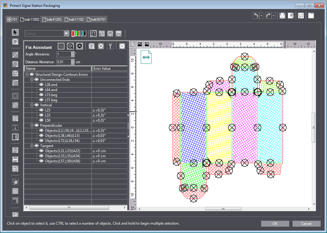
"Fix Assistant" |
The Fix Assistant lets you quickly find errors in the 1up.
The Fix Assistant analyzes the errors in the 1up and highlights them with circles. The problems are also shown in a list on the left.
This view remains on the screen as long as the button is active. In other words, you can simultaneously use other tools to fix the problems.
|
Controls in the Fix Assistant |
||
|---|---|---|
|
|
"Hatch shapes" This is where you can view and hide the display of hatched areas. |
|
|
|
"Toggle Auto Zoom" With this button enabled, the respective problem is zoomed in when you click an item in the list. |
|
|
|
"Toggle Auto Refresh" When this button is enabled, the view automatically jumps to the next problem as soon as a problem is solved. |
|
|
|
"Zoom Selected Issue" With this function you can zoom in on an issue manually if "Toggle Auto Zoom" is not enabled. First, select a problem in the list, then click this button. |
|
|
|
"Refresh" You can click this button to refresh the display in the Fix Assistant after having made changes. |
|
|
|
"Fix Selected Issue" Fixes the selected problem automatically. |
|
|
|
"Show Advanced Options" This is where you can set the test criteria for troubleshooting. Changed values take effect only when you click "Refresh". |
|
|
Objects Size Limit |
"Objects bigger than the limit are analysed" You can specify the minimum object size to be considered for analysis here. Value range: 0.001 to 40 cm. |
|
|
Small Creases |
"Creases below the limit are reported." Here, you can set the value below which creases are reported as a problem. Value range: 0.05 to 40 cm. |
|
|
Small Areas Limit |
"Areas below the limit are reported." You can set the value here below which areas are reported as a problem. Value range: 0.004 to 40 cm2. |
|
|
Angle allowance |
Deviations from the assumed angle (such as horizontal, vertical, right angle) up to the specified angle will be detected as an error. Example: an angle allowance of 2° results in lines intersecting at an angle between 88° and 92° to be regarded as vertical. An error is issued if the angle is not exactly 90°. Value range: 1° to 15°. |
|
|
Distance Allowance |
Distances between two lines or points up to the value specified here are recognized as an error. Value range: 0.001 to 5 cm. |
|
|
"Name" column |
All the problems found are listed below this item. |
|
|
"Error Value" column |
If applicable, this column displays the value responsible for classification as a problem. |
|
Back to Fix Assistant.
Return to Tool Bar in the "1up" Tab.
|
|
|
"Fix Tool Assistant" |
With the Fix Tool Wizard, you can make semi-automatic corrections to the 1up. This includes, for example:
You can apply fixing transformations to a whole design or just selected parts of it. Also, you can apply transformations in relation to selected part(s) and any other object in the design.
The fix wizard takes you through the following five steps:
•First step: "Parallel Fix Tool"
•Second Step: "Collinear Fix Tool"
Before starting the wizard, select the objects you want to fix. The "Fix Tool Wizard" handles the whole 1up if no object is selected.
The first four steps feature the following controls:
|
"Between any two objects" |
The wizard searches the whole drawing for problem lines. Each potential match that meets the "Error Allowance" is displayed in the 'Detected Relations' box. |
|
"Between selected objects" |
The wizard searches objects selected beforehand for problem lines. Each potential match that meets the "Error Allowance" is displayed in the 'Detected Relations' box. |
|
"Between selected and any other object" |
The wizard searches objects selected beforehand and the whole drawing for problem lines. Each potential match that meets the "Error Allowance" is displayed in the 'Detected Relations' box. |
|
Error Tolerance |
Use this section to define the error tolerance, i.e. the maximum deviation of a line from the correct position recognized as an error. You can use both numeric field and slider to indicate the desired allowance. The bigger the error tolerance, the greater the number of lines found. Depending on the step you are in, the error tolerance applies to parallel lines, collinear lines, arcs or the distance between two objects. |
|
Detect |
After you set the error tolerance, you must click "Detect" to display the correct number of problem lines. |
|
Detected Relations |
|
|
Table |
This table contains fields providing all information about potential transformation candidates. Click transformations suggested by the system in the table. |
|
"Object 1" |
This column displays all potential objects to which transformations will be applied. Use the check box in front of every object to select or deselect the suggested solutions. A selected object is highlighted with a bright blue line in the graphic on the left. |
|
"Object 2" |
This column indicates the objects the candidates in column "Object 1" seem to refer to, e.g. the parallel line or the second connecting line, depending on the step you are in. A selected object is highlighted with a yellow line in the graphic on the left. |
|
"failed" |
Indicates the error, i.e. the deviation between "Object 1" and "Object 2" to correct. The "Fix Tool Wizard" only detects errors that fall within the set "Error Allowance" range. |
|
"Fix Type" |
Shows the type of the relation that the objects will have after the required transformations are applied. |
|
Select all |
Selects all the check boxes for a transformation. |
|
Deselect All |
Deselects all the check boxes; there is no transformation. |
|
Preview All |
Selects all issues in the graphic on the left. |
|
Back |
This returns you to the previous step of the wizard. |
|
Next |
Applies the changes temporarily and guides you to the next step of the wizard. |
|
Skip |
Use this button to skip the current page and jump to the next one without applying the transformations of that page. |
|
Cancel |
Exits the wizard without applying the changes. |
First step: "Parallel Fix Tool"
This step checks objects for parallel relation errors. In this way, you can identify lines that are not exactly parallel or at right angles to each other. In "Error Tolerance", you set the maximum angle for the deviation still to be recognized as an error.
Second Step: "Collinear Fix Tool"
This step checks objects for collinear relation errors. In this way, you can identify lines that should form a contiguous line but have a slight offset. Using the error tolerance, you can control which offset between potential collinear lines (i.e. lines lying on a straight line) is to be included. The higher the value, the more lines will be found.
This step checks objects for tangent relation errors. You can use this step to find faulty arcs. The wizard checks if a line adjoining an arc could represent an arc tangent in this intersection point which would result in a more favorable transition. The radius of the arc is corrected so that tangent and line become identical if the actual arc tangent and the adjoining line match within the error tolerance. The left graphic displays a preview of the corrected arc with a dark blue line.
In this step, objects are checked for the presence of interrupted segments and missing relations. You can join single segments or segments with one broken end, thus making them act like a compound object. This way, you get a design with completely closed shapes. The other benefit is that in most cases the drawing keeps both its proportions and relations. In this case, the error tolerance represents the distance between the single objects that can be potentially joined.
The "Finalize" step applies final transformations to the whole design, such as adding relations, unconditionally merging objects or merging objects meeting specific conditions (having same attributes, adjoining in a point, etc.). These options are very helpful if you wish to apply transformations automatically to the whole drawing.
Although the "Fix Tool Wizard" is meant to automate the process of applying fixing transformations to currently used drawings, the whole procedure relies strongly on user settings, i.e. you are the one to choose the error tolerance as well as to decide which objects will be transformed when fixing.
Choose the "Auto Fix Tool" dialog instead if you want to carry out these steps faster and without manual intervention.
Back to Fix Assistant.
Back to Tool Bar in the "1up" Tab.
|
|
|
"Join Fix Tool" |
This tool has the same functions as the "Rule Joint" wizard page. See Fourth Step: "Rule Joint".
The Join Fix Tool is implemented as a separate dialog to facilitate repeatedly performing this fixing process.
Back to Fix Assistant.
Back to Tool Bar in the "1up" Tab.
|
|
|
"Auto Fix Tool" |
The Auto Fix Tool applies all the corrections automatically that you can also perform manually in the respective steps of the "Fix Tool Wizard" Dialog.
1.First, select the desired objects. The corrections will be applied to the complete 1up if no objects are selected.
2.Click the "Auto Fix Tool" button. A dialog displays where you can set the Scope and the Error Tolerance (angle tolerance and tolerance in cm analog to Steps Two to Four of the "Fix Tool Wizard" Dialog).
3.The corrections will be applied automatically when you click "OK".
Back to Fix Assistant.
Back to Tool Bar in the "1up" Tab.
|
|
|
"Replace Gaps" |
This option helps you replace any gaps in the 1up by an object (line, arc, etc.).
Click the "Replace Gaps" button in the toolbar. A dialog offering the following options opens:
|
Controls in the "Replace Gaps" dialog |
|
|---|---|
|
Objects |
|
|
All objects |
Applies Replace Gaps to all objects in the 1up. |
|
Selected objects |
Applies Replace Gaps only to selected objects in the 1up. Click "Select Now" to define the selective properties you want in the "Select objects" dialog. |
|
Options |
|
|
Gap |
Defines the minimum and the maximum length of the gap to be closed. |
|
Disable arc-to-circle conversion |
Disables converting an arc to a circle when gaps are being replaced. |
|
Delete duplicated objects |
Detects and deletes duplicated objects. |
|
Angle allowance |
Enter the maximum angle in this box to which the correction is to be applied. |
|
Distance precision |
Enter the maximum distance of parallel lines in this box to which the correction is to be applied. |
|
OK |
Applies Replace Gaps based on the settings you made and closes the dialog. A statistics message is issued. |
Back to Fix Assistant.
Return to Tool Bar in the "1up" Tab.
|
|
|
"Fix 1up by Layout" |
Use this tool to correct 1ups by the layout. Objects present in the layout may sometimes be absent in the 1up.
Proceed as follows:
1.Start by clicking the "Fix 1up by Layout" button in the toolbar.
2.The system displays a message with the applied corrections. The added parts are highlighted (selected) in the 1up drawing.
Back to Fix Assistant.
Back to Tool Bar in the "1up" Tab.


