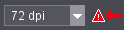
When you open the "Preview" tab, a flashing symbol with a red arrow next to the "Resolution" list box indicates that a high-resolution preview is also available.
You can view a preview of the job in the Prinect ImageViewer.
•You can switch from the preview resolution to the imagesetter resolution if "Halftone Pattern Proof" is licensed. See High-resolution preview.
This visual check lets you determine fast the content of a selected job. You can also use the preview as a layout and quality check and check before imaging whether all the image elements are present and fit into the page layout and whether the colors (process and spot colors) are assigned properly.
All the single separations (component jobs) are always present in a job if the jobs are bracketed when processed. For that reason, a preview of such a job comprises all the colors of the job.
Correspondingly, the preview shown is multicolored if there are colored images or elements in the job.
You can only open single separations (component jobs) in this mode.
Correspondingly, the preview always shows a single-colored view of the component job.
You can switch the preview to the original imagesetter resolution, for example, to check screening details in a higher zoom factor if "Halftone Pattern Proof" is licensed.
|
|
When you open the "Preview" tab, a flashing symbol with a red arrow next to the "Resolution" list box indicates that a high-resolution preview is also available. |
You can then switch to the imagesetter resolution in the list box and go back to the lower resolution when needed.
In a high resolution preview, the preview show the images "screened" to draw your attention to the fact that the page now displays in high resolution.
Preview options
Various tools are available for viewing and measuring the preview images. You can use these tools for the following actions:
•view information about the page size and resolution of the preview
•select single separations of process and/or spot colors or, in a sorted output, any combination of them.
•change the CMYK screen display of spot colors. The modified color data only affect the screen display and cannot be saved with the job data.
•measure the geometry data (length and angle)
•measure colors (pixels or dot percentage of a selectable section).
•scale the preview up to 10,000 %.
•use an ICC monitor profile for screen display (only for contones).
Layout of the "Prinect ImageViewer" window
The sheets or pages are shown as contone images on the left of the window. Scroll bars appear if the image pane is too small for displaying the preview because of the set zoom factor. You will find a toolbar below the graphic.
The right part of the Prinect ImageViewer window contains the setup and display pane for the preview. This is where you will find the following elements:
•"Info" tab with a progress bar for image processing and details about the resolution and size of the display
•"Navigator" tab for defining a clipped area
•all the process color/spot color separations in the job preview with names and color boxes and the option of showing or hiding them as needed and
•a display pane for the parameters of tools in the toolbar.
You will find buttons for maximizing / restoring the Printmanager window in this tab:
|
|
Click "Maximize" or "Restore" to detach the preview window from the Printmanager and maximize the screen display or restore it again to the Printmanager. |
A progress bar indicating how much of the image is already displayed is shown beside it:
The job name and details about the resolution (and the higher resolution option if you have it) and size of the display are shown below this.
The "Navigator" tab shows you an overview of the image that is loaded in the preview. You can use the Navigator as follows:
•If you set a zoom factor for viewing only a part of the preview image, the part you are viewing is highlighted by a box in the Navigator. When you shift this box, you also shift the section shown in the preview.
•If the entire image displays in the preview, you can define the size and position of a clipped area by drawing a bounding box or making the outer frame smaller in the Navigator.
Proceed as follows for a bounding box: The mouse pointer turns into a cross when you move it over the preview in the Navigator. Holding down the left mouse button, create a box over the part of the preview you want. When you release the left mouse button, the marked section of the Navigator preview is shown in the display pane in the left column. You can now change the size or position of the marked section in the Navigator.
Even if there already is a clipped area in the Navigator, you can define a new clipped area by drawing a new box outside the existing area. You can also draw a new box within an existing clip mask if you hold down the Alt key.
•If the Navigator has a box that is smaller than the full clipped area, you can move this box with the mouse. By doing so, you redefine your clipped area. To move the box, place the mouse pointer within the box and move it holding down the left mouse button.
You can also scale up the display of the preview with the zoom tool (magnifying glass). The box in the Navigator now also shows the section shown in the preview.
To change the clipped area, place the mouse pointer on a border or corner of the box. The mouse pointer now appears as a double arrow. Holding down the left button, you can now change the size of the box.
To move the clipped area, place the mouse pointer inside the box. The mouse pointer now appears as a hand. Holding down the left mouse button, you can now move the clipped area in the Navigator window.
It's quicker to move the mouse pointer to the position you want in the Navigator window and then click the left or right mouse button. The clip mask then moves to the position you clicked. The cross of the mouse pointer forms the center of the clipped area.
|
|
The toolbar also displays a rotating symbol while an image is being loaded to the screen because you cannot see the progress bar in the "Navigator" tab. See "Info" tab. |
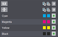
This lists all the process color/spot color separations contained in the open job with names and two color boxes in each case. The color boxes show what the color looks like in the preview image on the monitor and when printed.
Besides the color names and the icons for display color, you will also find the following columns:
|
|
Display of the preview colors |
|
|
Display of the output colors |
|
|
Showing/hiding separations |
You enable or disable these functions by clicking the appropriate box in each column. The boxes indicate their state as follows:
|
|
The option is enabled, the separation is displayed. |
|
|
The option is disabled, the separation is hidden. |
If you press the Ctrl key at the same time you click the "Show/hide separations" button, the button you clicked changes to the state you want. At the same time, all other "Show/hide separations" buttons switch to the opposite state of the button you clicked. In other words, the button you clicked is enabled and all other ones disabled or vice versa.
The preview image is recalculated every time you switch from showing to hiding a separation or vice versa. The progress bar appears with a message ("Image processing ...") while this is going on.
|
|
Spot colors in a job are shown below the process colors in the display pane for the separations on the right of the window. Spot colors are shown as CMYK values for the screen preview. The CMYK values that will replace a spot color can come from various sources. You can modify these values by clicking the button with the spot color name to display it in the "Preview/Color" dialog. See Changing the CMYK screen display of spot colors. A spot color that does not have a valid CMYK representation is shown by a striking color (generally bright green). This striking color is highlighted by question marks in the display pane for the separations. |
Changing the CMYK screen display of spot colors

Note: These settings refer solely to the screen display and do not affect the imagesetter output.
Click the button with the name of the spot color. A dialog opens where you can modify the screen display of the spot color.
The values for the CMYK representation of the spot color can be changed by means of the sliders or the input boxes.
The color currently set displays in the "Current Color" box. The last color set displays in the "Previous Color" box and the color taken from the color table in the "Default" box.
Click the "Default" button to use the color from the color table. The "OK" button is used to adopt the color which is currently set and "Cancel" is used to close the window without adopting the settings.
Confirm your settings by clicking "OK". The dialog closes.
You will find the toolbar at the lower edge of the preview window. The following tools are available from left to right:
|
|
Ruler for measuring geometry data |
|
|
Pipette for measuring colors |
|
|
Hand for shifting the image content |
|
|
Magnifying glass for zooming the preview |
|
|
Image clipping |
|
|
List box for selecting the scale factor |
|
|
Enable a line grid |
|
|
Add a separation |
|
|
List box for adding to front/back |
|
|
Mirror separations on the back |
|
|
Paper white simulation On/Off |
|
"Spot colors" |
Spot color view |
|
|
List box for selecting the page displayed (enabled only if job has multiple pages) |
|
"Refresh" |
Refresh image view |
|
"Cancel" |
Cancel preview |
You can measure the geometry data (length and angle) in the job preview. For example, this function allows you to check the positioning and size of objects.
Procedure:
1.Click the measurement tool ("ruler") in the toolbar.
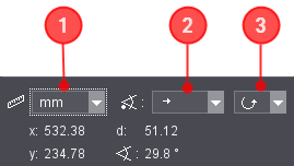
2.Set the unit of measure you want (pixel, inch or mm) in the list box (1) in the setup and display pane.
(3).To measure angles: In the list box for the angle origin (2) (arrow to the right/left/top/bottom) set the origin for measurement of the angle. Starting from this ray, the angle of the measured line is measured. In the example shown above, the origin is on the left and the ray to which angle measurement refers runs horizontally to the right.
(4).To measure angles: Set the rotational direction you want (counterclockwise/clockwise) in the list box for angle rotation (3). The angle is measured in the direction you selected.
5.Holding down the left mouse button, drag a line along the length you want to measure. Let go of the mouse button at your target. The measured line is kept until you draw a new one or change tool.
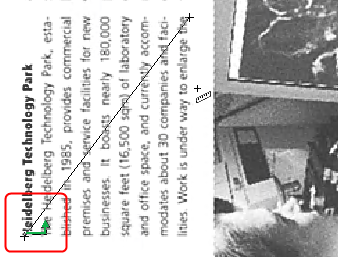

Note: Creating horizontal, vertical or diagonal lines is easier if you hold down the Shift key at the same time. These lines are drawn in steps of 45° seen from the baseline.
6.Read the geometry data of the measured line.

Note: The way the green arrow points at the origin of the measure tool symbolizes the direction of angle measurement.
•Position data of the starting point of the measured line (x and y)
•Length of the measured line (d) and
•angle of the measured line measured in the selected orientation from 0° to 359.9°.
You can determine the color recipe/area coverage in selected areas by means of the color data tool ("pipette").
Procedure:
1.Click the color data tool ("pipette") in the toolbar.

2.In the "Sample size" list box in the setup and display pane, set the area affected by color measurement (8 x 8 pixels, 16 x 16 pixels, Cursor Box, Cursor Box blinking or Visible area).
3.Click the spot to be measured in the image.
The color values for the selected area are measured.
4.Read the color data determined at the bottom right.
If there are spot colors in the preview image, you can also measure the spot color portions. You can switch over between the CMYK and the spot color values in the list box above the measured data.
|
|
If you selected a scale-up factor in which only a part of the preview image can be seen, you can click the tool for shifting the image content ("hand"). |
You can then move the image section by positioning the mouse pointer over a part of the image and holding down the left mouse button. You can now move the image section.
Moving the image section with the "hand" tool in the preview window lets you position it a great deal more accurately than moving it in the Navigator window.
The display is constantly updated, for that reason, "jerky" movements are possible (depends on the data volume of your job and on the performance of your computer). High-resolution data can take quite some time for the display to be refreshed.
|
|
You can scale up (to 1600 %) or down the display of the preview image by means of the zoom tool ("magnifying glass"). This function can help you check the register accuracy, for example, or assess critical points in the image or measure the length or angle. |
You can select from several set zoom factors in the list box besides the zoom tool. You can also enter your own zoom factor in the box and confirm it with ENTER. Any factors that you set separately are added to this list.
A preview always displays as an overview when a page opens the first time. You can change this display in several ways:
•By creating a box with the zoom tool and holding down the left mouse button. The defined clipped area appears scaled-up in the preview window.
•By selecting or entering a zoom factor in the list box.
|
|
The scale factor that gives you a full-screen preview of the complete image is tagged by this icon in the list box. |
•With the zoom tool and by clicking any spot in the preview image with the left mouse button. The next higher zoom factor in the list box is set. Vice versa, you can also scale down the display to the next value lower down by holding down the Alt key when you click (the plus sign in the mouse pointer changes to a minus sign). Any custom zoom factors are ignored with this type of zooming.
•In the context-sensitive menu (right mouse button) by selecting
·"Previous view" (zoom factor last set)
·"Next view" (this function undoes a zoom factor that was reverted using "Previous view" in the context-sensitive menu) or
·"Scale to fit" (entire page is displayed in the preview window)
|
|
The button for showing a line grid lets you show a pixel matrix in the preview for zoom factors of 500 % and higher. You can use this matrix, for example, for an analysis of screen problems. Click this button again if you wish to hide the matrix. |
|
|
The "Add file" dialog opens when you click the "Add separation" button. This dialog lets you load single bitmaps to the preview. If necessary, you can use "Look in" to go to the folder where the bitmap file you want is filed. Select the bitmap file and click "Open". You can select several files at the same time by holding down the Shift or Ctrl key and clicking the various items. If the file format matches the open job, the separation is loaded to the bitmap preview. It is assigned to the front or back as set in the list box on the right. |
Adding separations to the front or back
|
|
You can also load halftone bitmaps with exactly the same format as the open job to the bitmap preview. You can use this option, for example, to compare the halftone bitmap of a new separation with the original separation after a reprint. |
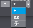
In the list box, first select the page the bitmap will be loaded to. The following options are available:
•Automatic front/back recognition ("plus sign"): Because of the properties saved in the bitmap file, Prinect Shooter automatically recognizes whether the separation is assigned to the front or the back.
•Add to front
•Add to back
|
|
These three buttons are enabled only if the front and back of a sheet are loaded. These buttons let you control the orientation of the back without rotating the front. At least one separation on the back must be visible for this. The pixels on the front are shown together with those on the back so that you think that the back is "shining through". |
Registration problems can occur if the page orientation or gripper edge are changed when the front and back of a signature are printed with the same form. To check this, you can change the orientation of the signature.
This function allows you to flip the back of the signature, depending on how the signature is used in the press (turn or tumble):
|
|
To view jobs with multiple pages, you can select the page you want in the "Page" list box or enter it in the text box. |

Note: The page specified refers to one "sheet". You cannot select single pages on a signature or the front or back side with this function.
You can reload the image preview with the "Refresh" button.
You can stop a running image processing by clicking "Cancel". Depending on your computer performance, it can take some time to calculate a preview with a large amount of data (large size and/or high resolution). You can then recalculate the preview, for example, with other options.
A right-click on the preview image displays a context-sensitive menu.
You will find the following commands:
•Previous view
You can use this command if you want to go back to the previous zoom factor for viewing the preview.
•Next view
This command is only available if you first selected "Previous view". It undoes this command.
•Scale to fit:
The entire page is displayed in the preview.
•Separation list on/off:
Use this function to show or hide the setup and display pane.
•Navigator blinking on/off:
You can set that the frame of the clipped area flashes in the Navigator window when you are in the "Navigator" tab. This can be useful if the color of the frame is barely different from the image motif of the Navigator window.
•Opaque effects
Table with keyboard shortcuts

Note: Some keyboard shortcuts can only be used with certain user interface settings or job conditions (e.g. if there are spot colors).
|
Key Combination |
Action |
|---|---|
|
Ctrl + "+" |
Select next scale up from the list. |
|
Ctrl + "-" |
Select next scale down from the list. |
|
Shift + "+" |
Show all process colors. |
|
Shift + "-" |
Hide all process colors. |
|
Alt + "+" |
Show all spot colors. |
|
Alt + "-" |
Hide all spot colors. |
|
Ctrl + mouse click on "visible"/"invisible" button (column header) in the pane for color separations |
Showing/hiding single separations If you hold down the Ctrl key and click several "visible/invisible" buttons one after the other, the clicked separations are switched to the opposite state. |