Cover Marks (Job-internal Cover Mark / 'CoverClippath')
Background Info about Cover Marks
Cover marks are used to cover a certain section of the background by an invisible white mask. The background objects lying below this mask then cannot be seen.
The "hierarchy" of the various "layers" is listed below to illustrate this:
•Background
•Cover mark
•Page/1up content
•Foreground
The job-internal cover mark and the "CoverClippath" mark differ in the way that the mask outline is defined.
Example for a cover mark:
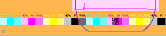
In packaging printing, the free spaces between the 1ups are used to place marks such as color control bars. The color control bar must be in the background in order for it to be covered by the 1up contents. However, the color control bar can be seen if the 1up contents are transparent. In such a case, you can use the job-internal cover mark, for example.
In the first graphic, you can see how the color control bar can be seen below the transparent packaging flap. In the second graphic, this part of the background is covered by the rectangular white mask of the job-internal cover mark.
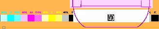
With cover mark
Job-internal Cover mark ('InternalMark')
This mark only exists as a job-internal mark and can only be a rectangle (for an example, see the graphic "With cover mark" page 507).
To set this mark, for example, on a press sheet, proceed as follows:
1.Go to the "Press Sheet" tab in the graphic window.
2.Using the measure tool, draw a rectangle whose size and position are that of the cover mark you want. (To do this, press the command and Shift keys and create the rectangle holding down the left mouse button. Release the mouse button first).
3.When the rectangle is created, an additional row appears at the bottom of the graphic window. A scroll bar with different icons appears if there is not enough room in the graphic window. Click the left or right arrow to view all the icons one after the other.

4.Click the button that displays as follows:

You have now created a rectangular cover mark. This mark is listed at the following points in the application:
•In the Browser window > "Internal Resources" in "Marks".
•In the Press Sheet Inspector > "Marks" tab > "Marks List"
(5).You can define a section of the mark that will be included in imaging without changing the size of the mark. Tips on operation can be found in the Expert Mode.
The "CoverClippath" mark can be found as a standard mark in the resources.
This mark is set for a selected 1up. If there is a clip path, the area within the clip path is filled white. If there is no clip path, the bounding box of the 1up will be filled white.
The special feature of this mark is that the area within every polygonal clip path can be masked. This makes packaging printing a typical field of application for the mark.
To set the "CoverClippath", proceed as follows:
1.Go to the "Folding Sheet/Assembly Block" tab in the graphic window.
2.Select the 1up you want to mask (left mouse button).
3.Right-click the selected 1up and then select "Page/1up Inspector" from the context-sensitive menu.
4.Assign the "CoverClippath" standard mark to the selected 1up (for details on assigning marks, see the Marks and Marks Resources ).
You have now created a white mask for the selected 1up that covers the area within the clip path.
(5).You can define a section of the mark that will be included in imaging without changing the size of the mark. Tips on operation can be found in the Expert Mode.
(6).You can apply the mark to all 1ups of the product part. To do this, click "Marks" > "Apply to all pages/1ups".

Note: You must select the 1up with a double click as the mark size generally corresponds to the 1up.
Create Cover Mark from CAD Lines
The tool can be used only if a frame is created.
A 1up must be selected before you can create a mark from the lines of the 1up. Afterwards, you can create the frame accordingly.
The Marks Editor opens when you click the tool. You can now change the mark as desired. The mark displays in the frame after you save and close the Marks Editor.
Define cover mark from line type for glue area
A 1up must be selected before you can create a mark from the line type of the 1up.
You can move the mouse pointer over CAD lines after you click the tool. The line type number displays in a tooltip. You can create a cover mark with a "click" if these lines produce a polygon.