
You can:
•Change the position of the folding sheet on the press sheet.
•Change the head, foot and back margins using the miniature scheme display.
•Apply the changes made here to all sheets of the same type.
Folding Sheet Name
This displays the folding sheet that is selected in the Browser window or in the graphic view. Details about the last folding sheet selected are shown if you haven't selected a folding sheet.
Position X/Y
This shows the position of the selected folding sheet on the press sheet. The bottom left corner of the paper is the zero point for both directions.
You can change the values for these positions manually.
Sheet Width/Height
Size of the folding sheet, based on the page size and gaps.
You can:
•Change the spacing for head, foot and back margins, see also "Master Pages" step > Master Pages.
You can also change these data in the Schemes step, Gaps and Master Pages.
Lenticular Printing Settings
Only displays if "Lenticular Printing Settings" is enabled in "File > Preferences > User Interface".
More details can be found in Lenticular Printing Settings .
Apply to folding sheets of same kind
Click this button if you wish to apply all the inputs/changes you made to all other folding sheets of the same type in the product part.
The "Marks" tab has identical features in the Press Sheet Inspector, Folding Sheet Inspector and Page Inspector. Make sure that the mark you have set displays in its proper inspector.
This is where you can position any marks for the selected folding sheet/assembly block/cutting die. You can also set cut marks, folding marks, folding crosses, folding sheet cuts and collating marks in this dialog. The width and height of the mark are shown in the "Expert Mode". In addition, you can define the clipping region of a mark (part that will be imaged) and/or imaging in the background. You can apply all the changes you made in this dialog to all surfaces and folding sheets of the same type in the product part.
You can find more details about marks in the chapter Working with Marks.
Surfaces (only in Press Sheet Inspector and Folding Sheet Inspector)
This is where you can select which marks will be listed:
For sheetfed offset: "All Surfaces" (front and back) or only for front or only for back
or
for web offset: "Top" and "Bottom" for web 1, web 2, web 3 or web 4
Grouping table
You can add or remove table columns (bold headings) with "Select Columns" in the context-sensitive menu. You can select columns in the "Select Columns" dialog that then displays and click the button you want. By defining the order in "View Columns", you define the column positions in the list from left to right. The column setup is saved in Prinect Signa Station and is available for all jobs.
The list can have the following columns that can be hidden if the inspectors window is not opened wide enough. The scroll bar displays in this case.
|
No. |
Order in the list. |
|
Icon |
The mark icon is displayed. |
|
Name |
The mark name is displayed. |
|
Reference Point |
This column displays the reference point for the mark. |
|
Hotspot |
Position of the hotspot in the mark (important for the mark to snap to position in relation to the reference point). |
|
Hotspot XY |
Coordinates of the hotspot position in the mark. |
|
Layer |
Shows whether the mark is set in the foreground or background of the page content. |
|
Absolute Offset |
Coordinates of the distance to the bottom left corner of the object for which a mark is set, for example, in the Folding Sheet Inspector for the folding sheet, in the Press Sheet Inspector for the paper, plate or subject. |
|
Border |
The part of the mark that is cut off is displayed as is shown later in "Clippath" in the inspectors window. |
|
Color |
This column displays the separation on which the mark will be printed. |
|
Mark Type |
Shows the mark type as was selected in the preferences or in the Marks Editor. |
|
Auto |
Tags automatic marks by a star. |
|
Surface (only Folding Sheet/Assembly Block Inspector and Press Sheet Inspector) |
This column displays the surface on which the mark is located: For sheetfed offset: Single-sided, all surfaces, front or back For web offset: "Top" and "Bottom" for web 1, web 2, web 3 or web 4 |
|
Parent (only Press Sheet Inspector) |
This shows whether the mark refers to the paper, plate or subject. |
|
Description |
Option for entering text for easier identification of the mark. You can edit the "Description" column for each mark. The text entered is saved for the placed mark and is available also after the job is reloaded. |
The folding and collating marks are the only automatically set marks that are shown in the list. The automatically set cut marks refer to the page/1up and are listed in the Page/1up Inspector > "Marks" tab (a page must be selected in the graphic window).
All the marks are displayed, irrespective of type and reference, in the graphic window in the "Folding Sheet/Assembly Block/Cutting Die" tab. For more details about setting marks, see Marks Resources .
The "Selected Mark" and "Expert Mode" sections are enabled when you select one or more marks in the list. These sections then show the data for the mark selected. In multiple selection, the data of the first mark selected are displayed. The selected mark is highlighted in the graphic window by a yellow square (red for automatic marks).
You can also change the order of the marks by clicking a mark in the Context-sensitive Menu. It may be a good idea to change the order in some situations because the mark listed first is the last one to be imaged and hides other marks below it.
Click the folder button on the right and select and add a mark from the resources in the "Choose Mark" dialog that then appears. You can also add marks by dragging and dropping them from the marks resources in the Browser window to the list. When you add marks, they are shown in the list and in the graphic view because they were set in relation to the folding sheet/assembly block. Marks added in this way always have "X=0/Y=0" as a reference point or "Lower left" in the other inspectors.
Note: Tiling marks always refer to the paper. For that reason, you can only set tiling marks with the Plate Template Editor or the Press Sheet Inspector. You can apply the selected mark(s) and its data to all surfaces (front or back) in the product part by clicking the icon below.
You can place a mark from the resources on the selected surfaces by clicking the icon below.

You can replace the selected mark(s) by a new one that you will select by clicking the icon below.

You can copy all selected marks to other surfaces of the selected object by clicking the icon below.

You can copy all marks on the front to the back of the selected object by clicking the icon below (only in the Press Sheet Inspector and Folding Sheet Inspector).

You can edit the selected mark with the relevant editor by clicking the icon below.

You can delete the selected mark(s) from the list by clicking the trashcan icon.
You can create or change marks as well using "Internal Resources > Marks" in the context-sensitive menu in the Browser window or in the "Marks Resources" tab in the Folding Sheet/Assembly Block Inspector, Press Sheet Inspector or Page/1up Inspector.
Cut Marks - Folding Marks - Collating Mark - Folding Crosses - Folding Sheet Cuts
The marks are automatically set for the folding sheet if you enable one of these options. They are removed if you disable the option. You can see which marks are set or removed in the "Marks List" and in the graphic window.
Cut marks (page-related) that you set or remove are shown and hidden respectively in the "Page Inspector > Marks".
Click the "Apply to folding sheets of same kind" button if the product part has other folding sheets that are to be changed.

Note: A mark type must be set again if you change the default for this mark type in the preferences for a particular job. You must do this so that the new mark displays in the graphic view, is added as an internal mark of the job and displays in the Browser window.
The following parameters of a mark selected in the list are enabled and some of them can be changed if needed:
This displays the resources group and the name of the selected mark. The resources group and the name of the first selected mark are shown if you selected several marks.
Automarks Set
This displays the automarks set from which the selected mark was taken.
This is where you can select the separation on which the selected mark that is not related to a specific color will be printed.
In addition, you can now set a mark on several color layers. You can define color layers as knockout.
•Color code
You can assign the mark to one or more color codes from the HD alphabet. For a description, see User-defined Color Mapping.

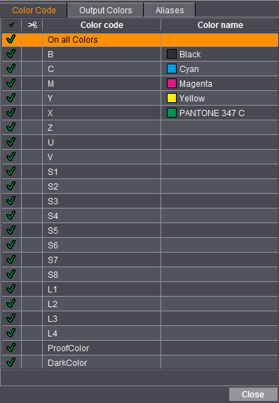
Click a row to disable or enable the color code. The default is Overprint. To set to Knock Out, you explicitly specify this by clicking in the second column (scissors symbol).
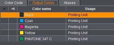
Marks can now be set directly to output colors. Select a mark that is not related to a specific color, open the "Output Colors" tab in the color selection and select the output color you want.
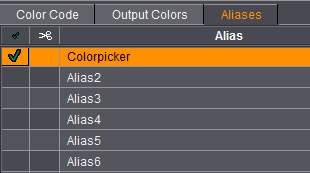
Assigning marks to aliases makes sense only in the Prinect workflow.
You can set marks to a color alias. You can then assign an output color to this color alias in the Prinect workflow (Prinect Prepress Manager).
You can select the name of the color alias as required in the table.
Example: You can set an ink pickup to an alias if it is to be placed in Prinect Signa Station although no contents (colors) are available so far. Later in the Prepress Manager you can then assign this to an output color. This means that it is no longer necessary to open the layout again in Prinect Signa Station after page assignment.

In the Press Sheet Inspector, Folding Sheet Inspector and Page/1up Inspector, you can set a line mark and/or text mark to "Dark Color" in the "Colors" group. As a result of this setting, this mark is always set automatically to the darkest separation of the job. If a job is output without black, a sheet lay mark, for example, would automatically be set to the darkest color in the job and output.

Note: Like in a non-separated job, "black" becomes the darkest color in a separated job with a black separation. The mark is set to the placeholder X only if there are spot colors in the job. In this case, you can select the darkest spot color manually in the "Colors" tab in the "Job" step.
You can find information about using aliases for the output of separations only with marks in Output of Separations Only with Marks.
Banner (for "Digital Web Press" only)
This is where you can select the layer (all, article, single banners) on which the mark will be placed.
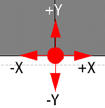
This option lets you select one of the reference points available for the selected mark. The bottom left corner of the folding sheet is the reference point, either "Lower left" or "x=0/y=0". Starting there, you move in single steps to the right (x direction) and/or to the top (y direction) like in an axis system.
In the Folding Sheet Inspector, the reference points have digits, e.g. "x=1/y=1" because every folding line in the scheme can be a reference point. In the Press Sheet and Page/1up Inspectors, words are used, e.g. "Lower middle".
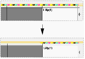
Examples:
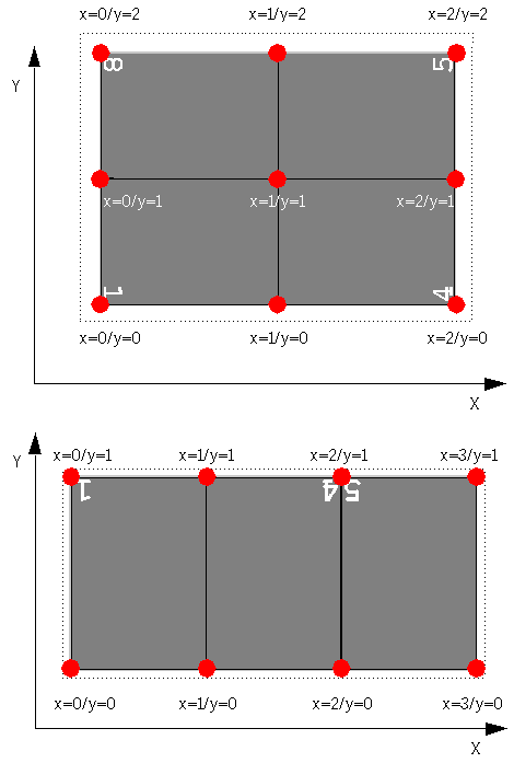
This option lets you position the selected mark as you want it in x/y direction in relation to its assigned reference point. The selected reference point can be, for example, x=1/y=0.
When this button is enabled, the offset values are modified/shown in relation to the last position of the selected mark. The offset values are modified/shown in relation to the reference point as described above when the button is disabled.
This function is also suited for multiple selection.

You can scale the selected mark between 10% and 500%. You can type the values directly into the input boxes using the keyboard or edit them stepwise using the arrow buttons when the cursor is located in one of the boxes. You can set the step size in the Preferences in "Defaults > Arrow Keys".
•"Keep proportions during scaling" button

|
When this button is enabled, the proportions do not change when scaling a mark (the input box for the Y direction is disabled). |

|
You can enter the values for height and width of the mark separately if the button is disabled. |
You can rotate the selected mark by the degrees specified.
You can also enter any angle you want in the "custom" box.
With orientation, the mark is rotated counterclockwise around the hotspot of the mark.
In this section, you can select whether the selected mark will be printed in the foreground or background of the page content.
The width and height of the selected mark is also specified. This value is defined by its scale and can now also be changed.
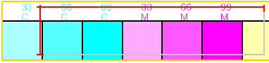
This option lets you cut off a part of the selected mark, for example, to print only a part of a color control bar. The value entered is cut off from the original size like a margin on the top, bottom, left or right. The original size of the mark, however, doesn't change. Values for left and right can already be available for the color control bar if the bar was already matched to the subject.
•Automated color control mark button


Prerequisite: Affects only color control marks.
Use this button to change a mark from a "Color Control Mark (with AutoClip)" to a "Color Control Mark" and be able to make changes to the mark margins.


You can define a clipping region for a mark in the graphic view after you click this button:
1.Select the mark in the list or double-click it in the graphic view.
2.You should zoom up the mark in the graphic view (approx. 200%).
3.Using the command + Shift keys and holding down the mouse button, you can now create a rectangular box within the mark (orange frame).

4.The measure tool button is enabled when you release the mouse button and then the two keys.
5.Click the button to add the values to the boxes on the left.
Apply to folding sheets of same kind
Click this button if you wish to apply all the inputs/changes you made in the "Marks" tab to all other folding sheets of the same type in the product part.
Apart from the "Internal Resources", the "Marks Resources" tab is identical to that in "Jobs & Resources > Marks" and is used to position marks to an active job by dragging-and-dropping them there.
You will also find the "Marks Resources" tab in the Press Sheet Inspector, Page/1up Inspector, Assembly Block Inspector and Plate Template Editor. Drag-and-drop works always the same way, what matters is from which inspector the marks come from.
The reference is also highlighted according to the type of mark (related to press sheet, folding sheet or page).
The following constellations are possible:
In the Press Sheet Inspector, you can select a mark and drag-and-drop it from there to the graphic window to the "Press Sheet", "Folding Sheet/Assembly Block/Cutting Die" and "Press Sheet List" tabs. You will see the possible reference points if you move a mark to the graphic window holding down the mouse button. The marks are always positioned on the press sheet and appear in the "Marks" tab in the Press Sheet Inspector.
In the Folding Sheet/Assembly Block Inspector, you can drag-and-drop a mark from there to the graphic window to the "Press Sheet", "Folding Sheet/Assembly Block/Cutting Die" and "Press Sheet List" tabs. You will see the possible reference points and the highlighted selected folding sheet/assembly block/cutting die if you move a mark to the graphic window holding down the mouse button. The marks are always positioned on the folding sheet/assembly block/cutting die and appear in the "Marks" tab in the Folding Sheet Inspector.
In the Page/1up Inspector, you can drag-and-drop a mark from there to the graphic window to the "Press Sheet", "Folding Sheet/Assembly Block/Cutting Die" and "Press Sheet List" tabs. You will see the possible reference points and the highlighted selected page if you move a mark to the graphic window holding down the mouse button. The marks are always positioned on the page/1up and appear in the "Marks" tab in the Page/1up Inspector.

Note: CoverClippath marks are page-related marks and, for that reason, can only be set with the Page/1up Inspector.
Tiling marks are paper-related marks and, for that reason, can only be set with the Plate Template Editor or the Press Sheet Inspector.