
The following marks were developed especially for packaging printing:
•"StationNumber"
•"InternalMark", cover mark as a job-internal mark
•"CoverClippath"
•Ink pickup bar with measure tool as a job-internal mark
The "StationNumber" mark can also be used in the "Montage" mode. The job-internal cover mark, the "CoverClippath" mark and the ink pickup bar with measure tool can be used in all other work modes as well.
Basically, all 1ups have station number "0" by default. This number, however, cannot be seen at first. Only when you assign "StationNumber" to a 1up can this hidden number be seen.
You can assign station numbers to the 1ups. In this way, each 1up can be clearly identified on the press sheet, independently of its content.
To benefit from this function, two steps are necessary:
•You must make the station numbers visible. To do this, you must assign the "StationNumber" mark to all 1ups that are to be numbered (see also the Step 1: Assigning the 'StationNumber' mark to the 1up).
•You must assign the station numbers (see also the Step 2: Assigning the station numbers). You do this by assigning a numbering sequence to all the 1ups or a group of selected 1ups. You set up the properties of the numbering sequence yourself (see the 'Assign Station Numbers...' dialog). In other words, you can form several groups of 1ups on your sheet, each with different numbering sequences.
The visible station numbers are very small on the screen. You can see the numbers better in one of the following ways:
•You can scale up the "StationNumber" mark to 400%, for example. You must then remember to reset the scaling again.
•You can use the PDF view of the press sheet. To do this, display the context menu in the graphic window > "Press Sheet" tab. Select "Print Press Sheet". Click the press sheet in the list of sheets and then click "View".
The "StationNumber" mark is a text mark that contains the "StationNumber" placeholder (see the Creating a Text Mark and Placeholders). You can also create any number of other text marks and assign them the "StationNumber" placeholder.
In the next two sections (section Step 1: Assigning the 'StationNumber' mark to the 1up and section Step 2: Assigning the station numbers), read how to work with the "StationNumber" mark.
Step 1: Assigning the 'StationNumber' mark to the 1up
Assign the "StationNumber" mark to all 1ups that are to be numbered. You can also assign a custom text mark that contains the "StationNumber" placeholder.
Proceed as follows:
1.Go to the "Folding Sheet/Assembly Block/Cutting Die" tab in the graphic window.
2.Select a 1up (left mouse button).
3.Right-click the selected 1up. Display the Page/1up Inspector from the context menu.
4.Assign the "StationNumber" mark to the selected 1up in the 1up Inspector (for details on assigning marks, see the Marks and Marks Resources ).
Make sure that the mark is in the foreground (the "Foreground" option must be set in the 1up Inspector > "Marks" tab > Expert Mode").
The station number appears as a black digit on the 1up. The "StationNumber" mark appears in the "Marks List". You can scale up the view, for example, to 400% to be able to see the mark better for tests.
The default station number is "0".
5.If you wish to assign "StationNumber" to all the 1ups, go to the "Marks" tab and click "To all pages/1ups" in "Apply Changes".
If you have several profiles, the mark is only applied in the profile with the selected 1up.
Note: You can also apply the "StationNumber" mark (plus any inputs made in the "Marks" tab) to a group of selected 1ups. To do this, first select the 1up with the "StationNumber" mark. Then select the 1ups to which the mark will be applied. Click "Apply to selected pages/1ups". This also works if you selected several 1ups in different profiles.
See also Page/1up Inspector .
You can also apply the "StationNumber" mark (plus any inputs made in the "Marks" tab) to a group of selected 1ups. To do this, first select the 1up with the "StationNumber" mark. Then select the 1ups to which the mark will be applied. Click "Apply to selected pages/1ups". This also works if you selected several 1ups in different profiles.
Step 2: Assigning the station numbers
In the 2nd step, you must now assign a station number to all 1ups with the "StationNumber" mark. You can assign station numbers in the folding sheet/assembly block/cutting die view and in the press sheet view.
Proceed as follows in the folding sheet/assembly block/cutting die view:
1.Go to the "Folding Sheet/Assembly Block/Cutting Die" tab in the graphic window.
(2).This step is necessary if you would like to divide your 1ups into groups with different numbering sequences. Then you must select groups of 1ups that will be assigned a numbering sequence later. Select a 1up by clicking it with the left mouse button while holding down the Ctrl key.
3.Right-click the graphic window.
4.Select "Assign Station Numbers..." from the context menu.
5.Set the station numbers to suit your needs (for operation, see the 'Assign Station Numbers...' dialog).
You will see the black station numbers in the graphic window.
Proceed as follows in the press sheet view:
(1).This step is necessary if you would like to divide your 1ups into groups with different numbering sequences. Then you must select groups of 1ups that will be assigned a numbering sequence later. Go to the "Folding Sheet/Assembly Block/Cutting Die" tab in the graphic window to select your 1ups. Select a 1up by clicking it with the left mouse button while holding down the Ctrl key.
2.Go to the "Press Sheet" tab in the graphic window.
3.Right-click the graphic window. If you selected several 1ups in the "Folding Sheet/Assembly Block/Cutting Die" tab, you must click the area beyond the plate with the right mouse button. If you don't, the selection of 1ups will be lost.
4.Select "Assign Station Numbers..." from the context menu.
5.Set the station numbers to suit your needs (for operation, see the 'Assign Station Numbers...' dialog).
You will see the black station numbers in the graphic window.
'Assign Station Numbers...' dialog
In the "Station Numbers" dialog, you can set the station numbers as you need them.
Start this dialog in the graphic window > "Folding Sheet/Assembly Block" tab or "Press Sheet" tab > "Assign Station Numbers..." in the context menu.
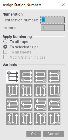
•"Numeration": This is where you set the number of the first 1up and the increment.
•"Apply Numbering":
·"To all 1ups": All the 1ups will be assigned numbers.
·"To selected 1ups": Only the selected 1ups will be assigned numbers in ascending order. All other 1ups keep their numbering. In this way, you can group 1ups, all of which have their own numbering sequences.
Each numbering sequence starts with the number that you entered in "First Station Number". Each numbering sequence has its own "increment" and its own "variant".
You can only set this option if you selected one or more 1ups beforehand in the graphic window > "Folding Sheet/Assembly Block" tab.
If "To all 1ups" is set, you now have the added option of numbering all the press sheets in the product part.
Numbering always starts on the first press sheet and is applied only to the selected surface (front or back).
The station indices are also modified along with the station numbers if "Modify Station Indices" is also set.
•"Variants": This is where you set the starting point and run direction of the station numbers.
Usage in the 'Imposition' Mode to keep folding sheets distinct
You can use the "StationNumber" in the "Imposition" mode for the order number of the folding sheet.
1.In the "Marks" step, enable "Folding Sheet Label 1" in "Automatically Placed Print Control Marks".
2.Assign it the "StationNumber" text mark using the "Choose selected automatic mark from the resources" icon.
3.We recommend that you scale the mark up to 300-400 % to make it easier to read.
Cover Marks (Job-internal Cover Mark / 'CoverClippath')
Background Info about Cover Marks
Cover marks are used to cover a certain section of the background by an invisible white mask. The background objects lying below this mask then cannot be seen.
The "hierarchy" of the various "layers" is listed below to illustrate this:
•Background
•Cover mark
•Page/1up content
•Foreground
The job-internal cover mark and the "CoverClippath" mark differ in the way that the mask outline is defined.
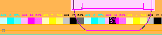
Example for a cover mark:
In packaging printing, the free spaces between the 1ups are used to place marks such as color control bars. The color control bar must be in the background in order for it to be covered by the 1up contents. However, the color control bar can be seen if the 1up contents are transparent. In such a case, you can use the job-internal cover mark, for example.
In the first graphic, you can see how the color control bar can be seen below the transparent packaging flap. In the second graphic, this part of the background is covered by the rectangular white mask of the job-internal cover mark.
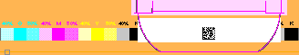
With cover mark
Job-internal Cover mark ('InternalMark')
This mark only exists as a job-internal mark and can only be a rectangle (for an example, see the graphic "With cover mark" page 577).
To set this mark, for example, on a press sheet, proceed as follows:
1.Go to the "Press Sheet" tab in the graphic window.
2.Using the measure tool, draw a rectangle whose size and position are that of the cover mark you want. (To do this, press the command and Shift keys and create the rectangle holding down the left mouse button. Release the mouse button first.)
3.When the rectangle is created, an additional row appears at the bottom of the graphic window. A scroll bar with different icons appears if there is not enough room in the graphic window. Click the left or right arrow to view all the icons one after the other.

4.Click the button that displays as follows:

You have now created a rectangular cover mark. This mark is listed at the following points in the application:
•In the Browser window > "Internal Resources" in "Marks".
•In the Press Sheet Inspector > "Marks" tab > "Marks List".
(5).You can define a section of the mark that will be included in imaging without changing the size of the mark. Tips on operation can be found in the Expert Mode.
The "CoverClippath" mark can be found as a standard mark in the resources.
This mark is set for a selected 1up. If there is a clip path, the area within the clip path is filled white. If there is no clip path, the bounding box of the 1up will be filled white.
The special feature of this mark is that the area within every polygonal clip path can be masked. This makes packaging printing a typical field of application for the mark.
To set the "CoverClippath", proceed as follows:
1.Go to the "Folding Sheet/Assembly Block" tab in the graphic window.
2.Select the 1up you want to mask (left mouse button).
3.Right-click the selected 1up and then select "Page/1up Inspector" from the context menu.
4.Assign the "CoverClippath" standard mark to the selected 1up (for details on assigning marks, see the Marks and Marks Resources ).
You have now created a white mask for the selected 1up that covers the area within the clip path.
(5).You can define a section of the mark that will be included in imaging without changing the size of the mark. Tips on operation can be found in the Expert Mode.
(6).You can apply the mark to all 1ups of the product part. To do this, click "Marks" > "Apply to all pages/1ups".

Note: You must select the 1up with a double click as the mark size generally corresponds to the 1up.
Create Cover Mark from CAD Lines
The tool can be used only if a frame is created.
A 1up must be selected before you can create a mark from the lines of the 1up. Afterwards, you can create the frame accordingly.
The Marks Editor opens when you click the tool. You can now change the mark as desired. The mark displays in the frame after you save and close the Marks Editor.
Define cover mark from line type for glue area
A 1up must be selected before you can create a mark from the line type of the 1up.
You can move the mouse pointer over CAD lines after you click the tool. The line type number displays in a tooltip. You can create a cover mark with a "click" if these lines produce a polygon.
Ink Pickup Bar with Measure Tool
This mark only exists as a job-internal mark.
The size of the mark is dynamic when you create an ink pickup bar in the Ink Pickup Bar Editor that you display with "File > Create Resource > New Mark > Ink Pickup Bar...". In other words, the mark adapts itself to the context (e.g. subject) in which it is set.
By contrast, if you create an ink pickup bar using the measure tool, you define the size of the mark at the start. The size stays the same when creating the mark, i.e. the mark content must be fitted to the mark size.
To create an ink pickup bar with the measure tool, proceed as follows:
1.Go to the "Press Sheet" tab in the graphic window.
2.Using the measure tool, draw a rectangle whose size and position are that of the ink pickup bar you want. (To do this, press the command and Shift keys and create the rectangle holding down the left mouse button. Release the mouse button first.)
3.When the rectangle is created, an additional row appears at the bottom of the graphic window and includes the following button:

Click this button.
The Ink Pickup Bar Editor opens, displaying the rectangle you created.
4.Create your ink pickup bar and click "Save".

Note: You can choose to define a strip-based or an ink zone-related ink pickup where the transparent areas of the press sheet are determined automatically and the ink pickup elements are placed into the transparent areas of the press sheet (facilitates the ink pickup, in particular for Packaging printing with spot colors).
You can find a description on how to use the Ink Pickup Bar Editor in the Ink Pickup Bar Editor .
The editor started through the measure tool differs from the normal Ink Pickup Bar Editor as follows:
The "Width" and "Height" boxes are dimmed as the size of the mark cannot be changed. They only show the size of the mark. The height of each color bar is matched automatically if you add or remove additional colors in the "Choose Color Layer" list.