
The 3D Presenter Context Menu (Packaging Pro)
Prerequisite: This function is contained in Prinect Packaging Pro.
|
The 3D Presenter Context Menu |
||
|---|---|---|
|
View Options |
Opens the Dialog "View Options". |
|
|
View Images |
You specify the PDF files loaded to the project as images in the "Content" step of Prinect Signa Station. Here, you can show and hide them. |
|
|
Select viewed image |
Opens a submenu where you can select the images to be viewed. Clicking the arrow next to any of the following elements will open a list with image contents you can choose from. |
|
|
No clipping |
|
|
|
1up clipping |
|
|
|
Instance on Layout |
|
|
|
|
|
|
|
|
Browse Layouts... |
A dialog displaying the entire layout opens. Click a 1up to have it displayed in the 3D view. |
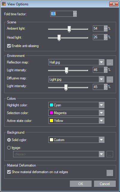
In the "View Options" dialog that you can invoke in the context menu, you can define how to visualize the movements of the 3D drawing.
Right-click the canvas and select "View Options" in the context menu. The following dialog displays:
Object illumination is calculated by way of the Phong shading model. You can set individual parameters to customize the view.
The Phong shading model is an approximation that is not based on physical fundamentals but offers very good results with smooth surfaces.
There is a spot light source in the environment that appears like a head light on the observer's head. Its light always shines from the observer's direction. This is the "Head light". Its light causes reflections on the surface.
The second light source is the ambient light. It shines uniformly from all directions. You can set its characteristics in the "Environment" area.
The brightness of a particular point of the object is made up of the ambient light, the light scattered by the head light, and the light reflected by the head light.
For ambient and head light, you can also adjust the influence of the environmental room on the illumination of the object and thus increase its realistic appearance. You can specify which image is to be visible in reflective surfaces. You can also simulate dark and bright areas in the room, e.g. a large window, by way of the diffusive map.
|
Controls in the Dialog "View Options" |
|
|---|---|
|
Fold time factor |
This is where you can set the speed of the animation. The fold time is multiplied with this factor. The greater the value, the slower runs the fold animation. Value range: 0.3 to 10. |
|
Scene |
|
|
In this area, you define the brightness of the two light sources (ambient and head light). |
|
|
Ambient light |
The ambient light illuminates the object evenly without being affected by the object's geometry. It does not cause any reflections. The higher the value, the higher is the basic brightness of the object. |
|
Head light |
The head light always shines from the observer's direction. When it hits the object, part of it will be scattered, and part of it will be reflected directly. In this way, the head light depends on the geometry of the object, and on the alignment of the object relative to the observer. Reflections form on surfaces that are perpendicular to the direction of observation. The higher you set the value for the head light, the stronger is the reflective effect. |
|
Enable anti-aliasing |
Here, you can enable anti-aliasing here or disable it in case of viewing issues. |
|
Environment |
|
|
In this group, you fine tune the environment settings. |
|
|
Reflection map |
This is where you specify an image to be reflected in reflective surfaces of the object. The default is "Hall.jpg" representing a living room: 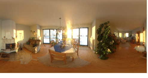
If you want a different environment, click the button with the three dots and browse for the desired image. Ideally it should be a spherical image. Note: The reflection map is visible only on mirroring surfaces. On matte surfaces, this image and the pertaining sliders have no effect. Information about the surface is contained in the print job. Prinect Signa Station forwards this information to Packaging Pro. But you can also edit the material properties and specify a reflective surface in Packaging Pro. See Dialog "Drawing Properties". |
|
Brightness |
This is where you set the brightness of the reflection map. |
|
Diffusive map |
This profile simulates a more complex ambient light. The default profile "Light.jpg" is to represent a room of 3 x 6 meters with a window on the smaller wall. |
|
Brightness
|
This is where you define the brightness of the light determined by the diffusive map. The illumination of the object depends on its position in the room and its geometry. Reflections occur, for example on curved surfaces. The illumination does not depend on the observer's position. There are no strong reflections like with the head light. |
|
Design Colors |
|
|
Defines the colors in the graphical preview of the 3D Presenter. You can select a color from the list box with predefined colors or you can define a custom color. |
|
|
Highlight color |
Defines the color an object, when pointed to, will have. |
|
Selection color |
Defines the color of a selected object. |
|
Active state color |
Defines the color of the drawing if an inserted external 3D object is to be placed and its ultimate position is to be determined. |
|
Preview Background |
|
|
Defines the background of the graphical preview in the Preview mode. |
|
|
Color |
Enable this option if you want to use a color as background. Choose the color you want in the list box. |
|
Image |
You can choose an image for a background and define its storage location with the "Browse" button. |
|
Material Deformation |
|
|
Show material deformation on cut edges |
Specify if material deformation on the cutting and embossing edges is to be shown. Click the button with the three dots to edit the appearance of the embossing edge. The "Edit Edge Emboss Appearance" dialog opens. See Edit Edge Emboss Appearance. |
In this dialog, you can edit the edge emboss appearance as you like. You can define different types of edge embossing for the die side and the counter die side.
To open the dialog, right click the canvas in the "3D View" tab and select the "View Options" item in the context menu. Then click the button with the three dots.
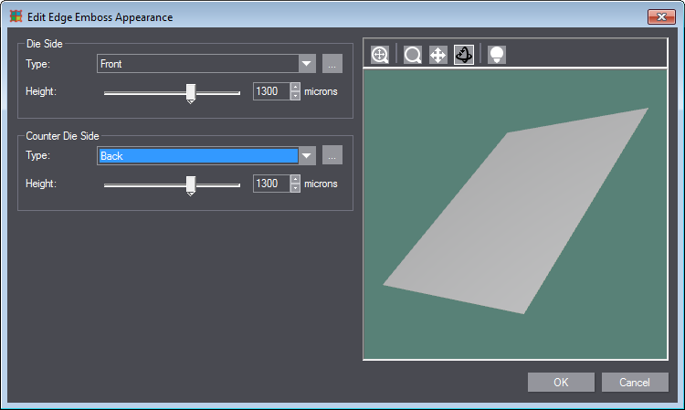
1.In the "Type" list box, select how the embossing is to be.
The following picture shows lines in the styles "Creasing" (top), "Perforating" (middle) and "CutCrease" (bottom) in the 3D view.
·No material deformation was chosen in [1]. The "Perforating" line is invisible.
·Material deformation was chosen in [2]; "Front" was chosen as Type.
·"Back" was chosen as Type in [3].
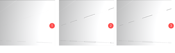
2.Specify the perforation depth in "Height". The higher the value, the better the perforation is visible. The values can range between 8 micrometers and 2000 micrometers (= 2 mm).
3.You can press the button with the three dots to fine tune the edge shape. The "Edit Bump Shape" dialog displays with the following parameters:
|
Controls in the dialog "Edit Bump Shape" |
|
|---|---|
|
List box |
•Back •Front |
|
Border Width Border Width |
Border Width Indicates the width of the entire border. The values range between 0 and 1 cm. |
|
Slope Offset |
Slope Offset |
|
Height |
Height |
|
Slope Grade |
Slope Grade |
|
Slope Blur Width |
Slope Blur Width |
|
Slope Power |
Slope Power |
Back to Dialog "View Options".
Back to Context Menus.