To edit the properties of a drawing or to delete a drawing, right click the tab name. A context menu with the following items appears:
|
Context menu of the tab name |
|
|---|---|
|
Properties |
This is where you can edit the name of the drawing and material properties such as thickness and grammage. See Dialog "Drawing Properties". |
|
Delete Drawing |
This lets you delete a drawing in the project. |
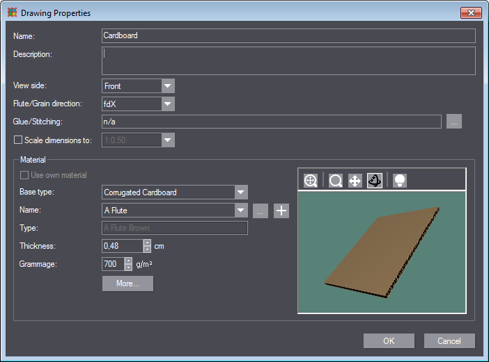
In the "Drawing Properties" dialog, you can edit the material properties of the 1up. To open this dialog, right click the tab name and select "Properties" in the context menu. The following dialog opens:
|
Controls in the "Drawing Properties" dialog |
||
|---|---|---|
|
Name |
This lets you rename the drawing. |
|
|
Description |
You can enter a comment on the drawing into this box. |
|
|
View |
Defines the drawing side that is displayed on the canvas. •Front •Back This item is omitted for a 3D view. |
|
|
Flute/Grain direction |
Set the flute/grain direction here. •fdY •fdX |
|
|
Glue/Stitching |
This is where the glue/stitching points of the box are shown. Click the button with the three dots to define them in a separate dialog. See "Manufacturing joints" dialog. |
|
|
Scale dimensions to |
Only operable if the drawing contains dimensions. This is where you can specify how dimensions are scaled when exporting the drawing: •1:1 •Edit scaling options |
|
|
Material |
||
|
Use own material |
Overrides all the material defined for the project and lets you use a different material for the current drawing. NOTE: The option is not available if a specific material has already been specified for the entire project. |
|
|
Base type |
Define the material type the current material is to be based on. |
|
|
Name |
Specify the material for the project here. |
|
|
|
|
Click this button if the desired material is not contained in the list. The Materials Catalog opens. You can edit or create materials here. |
|
|
|
Append this material to the catalog. The "New Material" dialog displays. See "New Material" dialog. |
|
Type |
|
|
|
Thickness |
|
|
|
Grammage |
|
|
|
More ... |
See |
|
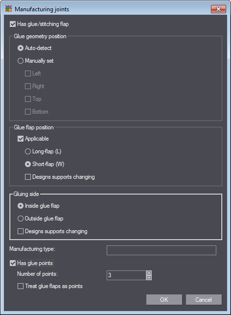
In the "Manufacturing joints" dialog you can specify the position of glue and stitching flaps. To open this dialog, right click the tab name of the 1up. Choose "Drawing Properties" and click the button with the three dots in "Glue/Stitching". The following dialog displays:
|
Controls in the "Manufacturing joints" dialog |
||
|---|---|---|
|
Has glue/stitching flap |
Enable this option if you want to specify glue or stitching flaps. The items "Glue geometry position", "Glue flap position", and "Gluing side" are enabled only then. |
|
|
Glue geometry position |
||
|
This is where you select on which side the flap is to be. |
||
|
Auto-detect |
The position is set automatically. |
|
|
Manually set |
Select the position (left, right, top, bottom). |
|
|
Glue flap position |
||
|
In this area you specify if the glue flap is to be on the long side or the short side of the 1up. |
||
|
Applicable |
Enable this option if the box has a glue flap. |
|
|
|
Long-flap |
The glue flap is on the long side. |
|
|
Short-flap
|
The glue flap is on the short side. |
|
|
Design supports changing |
|
|
Glue side |
||
|
This is where you specify the side of the flap to which glue is to be applied. |
||
|
Inside glue flap |
The glue side is towards the box inside. |
|
|
Outside glue flap |
The glue side is towards the box outside. |
|
|
Design supports changing |
|
|
|
|
||
|
Manufacturing type |
Type a name for your settings here. This will make it easier to search in the list box of the "Drawing Properties" dialog. |
|
|
Has glue points |
Enable this option if the box has glue points. This will enable the following items: |
|
|
|
Number of points |
Enter the number of glue points. |
|
|
Treat glue flaps as points |
|
In this dialog you can set scaling factors for the dimensions. Do the following to open the dialog:
1.Right-click the tab name.
2.Choose "Properties...". The "Drawing Properties" dialog displays.
3.Enable the "Scale dimensions to" option.
4.Select "Edit scaling options" in the list box. The following dialog displays:
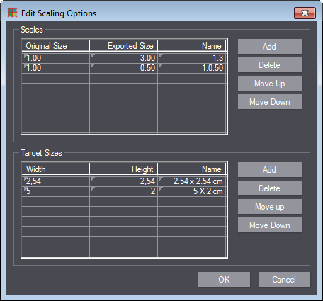
The dialog offers two methods of creating scaling rules:
•by relative aspect ratios (in Scales)
•by typing absolute values (in Target Sizes).
Both methods work autonomously, and patterns can be created independently.
This lets you ensure, for example, that the drawing matches the desired paper size. For example: define a target size of 210x297 if you want to use A4 in landscape orientation.
To create a new relative scale factor, proceed as follows (this also applies to Target Sizes):
1.In "Scales" click "Add". An empty row appears in the list.
2.Edit the respective values for the scaling factor in the "Original Size" and "Exported Size" columns.
3.(Optional) Type a name for the scaling factor in the "Name" column. TIP: You can enter any name you wish. A name is generated from the values you typed in the "Original Size" and "Exported Size" columns if you do not enter a specific name for the scaling rule.
4.(Optional) Repeat steps 1- 3 to create more scaling patterns.
5.Click "OK" to use the new scaling patterns.
6.Select the pattern you want in the list box of the "Drawing Properties" dialog.
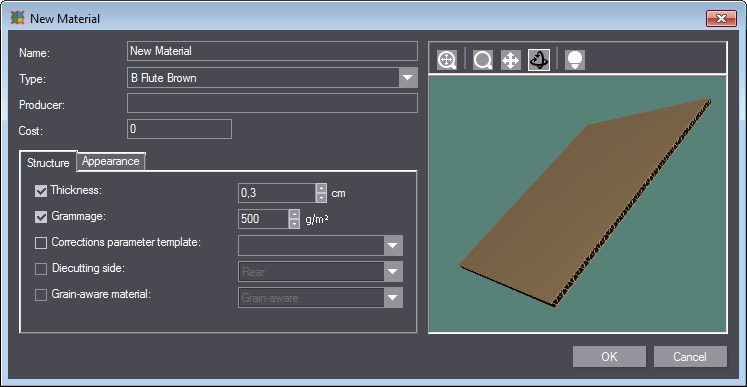
You can create a new material in this dialog. Invoke the dialog as follows:
1.Right-click the tab name.
2.Choose "Properties...". The "Drawing Properties" dialog displays.
3.Click the plus sign in the "Material" area. The following dialog displays:
|
Controls in the Dialog "New Material" |
||
|---|---|---|
|
Name |
Enter a name for the new material in this box. |
|
|
Type |
Select the material type from the list box. The types are grouped by base types "Folding Carton Cardboard", "Corrugated Cardboard", and "Inverted Corrugated Board". The material type defines the fundamental technical properties of the material. |
|
|
Manufacturer |
As an option, enter the manufacturer of the material in this box. |
|
|
Cost |
As an option, enter the cost for 1000 kg of the material here. |
|
|
Tab "Structure" |
||
|
Thickness |
Material thickness in cm. |
|
|
Grammage |
Grammage of the material in g/m2 |
|
|
Corrections parameter template |
This is where you can select a parameter template if available. Corrections are made to the material on the basis of this template. |
|
|
Diecutting side |
This is where you can define which side is used as die side. |
|
|
Grain-aware material |
This is where you can define if the grain or flute direction of the material is to be considered. |
|
|
"Appearance" tab |
||
|
In this tab, you can edit the appearance of the front and of the back independently. |
||
|
Front |
Enable this option to edit the appearance of the front. You can then use the list box to select another surface from the catalog. |
|
|
|
|
"Browse in the catalog" Opens the dialog "Material Surface Appearances" where you can browse the catalog more conveniently. See Dialog "Material Surface Appearances". |
|
|
|
"Customize Appearance" Opens the "Customize Appearance" dialog where you can edit the current surface. See Dialog "New Surface"/"Customize Appearance". |
|
Back |
Analog to "Front" |
|
|
Edge |
This is where you can edit the appearance of the edge. Proceed as with the "Front". |
|
Dialog "Material Surface Appearances"
In this dialog, you can select, edit, create or delete material surfaces. You can invoke the dialog as follows:
1.Right-click the tab name.
2.Choose "Properties...". The "Drawing Properties" dialog displays.
3.Then click the button with the three dots next to "Name". The "Material Catalog" dialog displays.
4.Click the "New" button. The "New Material" dialog displays.
5.Click the "Appearance" tab.
6.Enable the "Front" option.
7.Then click the button with the three dots "Browse in the catalog". The following dialog displays:
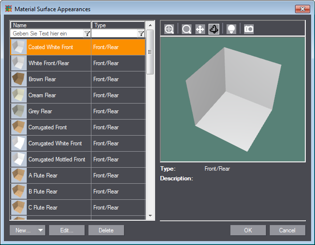
You can browse the surfaces in the list by typing keywords in the "Name" and "Type" text boxes.
|
Controls in the Dialog "Material Surface Appearances" |
|
|---|---|
|
New/Clone |
Opens another dialog where you can create a new material surface. See Dialog "New Surface"/"Customize Appearance". Clicking the triangle in the button will change its function to "Clone". The same dialog as with "New" opens but the properties of the current surface are already preset. |
|
Edit |
|
|
Delete |
|
|
Preview pane |
|
|
Next to the known view control buttons, the 3D preview also offers the following buttons: |
|
|
|
A new dialog opens where you can set the preview illumination. See "View Options" dialog. |
|
|
Takes a snapshot of the current view. The snapshot will then appear as a preview in the material catalog. |
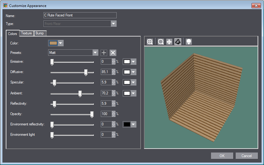
Dialog "New Surface"/"Customize Appearance"
In this dialog, you can create a new material surface or edit an existing one. There are various ways to open this dialog: For example:
1.Right-click the tab name.
2.Choose "Properties...". The "Drawing Properties" dialog displays.
3.Click the "More..." button. The "Drawing Material Properties" dialog displays.
4.Click a button with the sliders in the "Appearance" group. The dialog "Customize Appearance" displays; it is identical with the dialog "New Surface":
|
Controls in the Dialog "New Surface"/"Customize Appearance" dialog |
|
|---|---|
|
Name |
This shows the name of the surface. You can type a name here when creating a new surface. |
|
Type |
This shows the type of the surface. You can set a type here when creating a new surface. |
|
"Colors" tab |
|
|
Color |
|
|
Preferences |
|
|
Emissive |
|
|
Diffusive |
|
|
Specular |
|
|
Ambient |
|
|
Reflectivity |
|
|
Opacity |
|
|
Environment reflectivity |
|
|
Environment light attenuation |
|
|
"Texture" tab |
|
|
Plain |
|
|
Image |
|
|
Text |
|
|
Angle |
|
|
X step |
|
|
Y step |
|
|
"Bump" tab |
|
|
Plain |
|
|
Height map |
|
|
Image |
|
|
Bump intensity |
|
|
Width |
|
|
Height |
|
|
Angle |
|
In this dialog you can set the illumination for the 3D preview. You can invoke this dialog from previews in several other dialogs by clicking this button ![]() .
.
The following dialog displays:
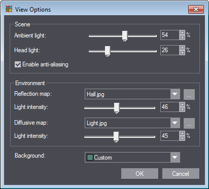
The settings this dialog offers are identical with those in the "View Options" and are explained there. See Dialog "View Options".
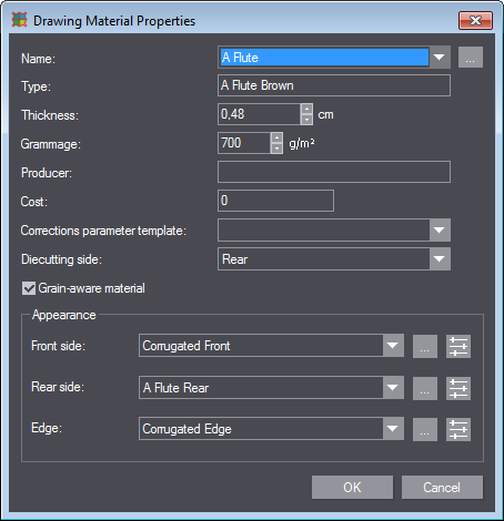
"Drawing Material Properties" dialog
You can view or edit the following packaging material parameters in this dialog: You can invoke the dialog as follows:
1.Right-click the tab name.
2.Choose "Properties...". The "Drawing Properties" dialog displays.
3.Click the "More..." button. The following dialog displays:
|
Controls in the "Drawing Material Properties" dialog |
||
|---|---|---|
|
Name |
|
|
|
Type |
|
|
|
Thickness |
|
|
|
Grammage |
|
|
|
Manufacturer |
|
|
|
Cost |
|
|
|
Corrections parameter template |
|
|
|
Diecutting side |
Choose the side where cutting is to occur (front, back). |
|
|
Grain-aware material |
Enable this option if the grain direction is to be considered when using the material in a project. |
|
|
Appearance |
||
|
|
|
|
|
|
|
|
|
Front |
|
|
|
Back |
|
|
|
Edge |
|
|