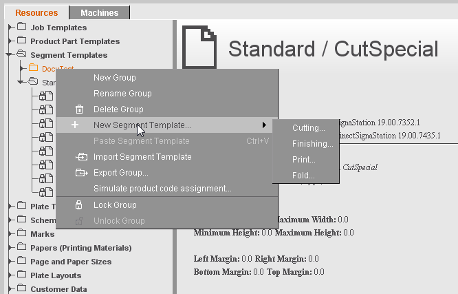
Use this editor if you wish to create/edit a segment template that is saved as a resource in "Segment Templates". Segment templates let you group jobs of a gang job on the press sheet to areas with the same processing.
You can create three different types of segment templates:
•Cutting
•Finishing
•Fold
The setting options in the tabs vary according to the type.
The following is valid for all segment templates:
•They must be assigned to a segment template group (assignment in the plate template is done via this group).
•A product code filter must be defined. The product codes determine when a segment template will be used.
See Types of Segment Templates for an explanation of the types of segment templates.
This tab displays the relevant contents for each of the segment types. Above all, it is important that you set the product code here that lets you define the cases in which exactly this segment template will be used.
If you want to create different segment templates for a product code and differentiate them by specifying the delivery quantity, all segment templates for this product code must have a set delivery quantity.
Example: You want to control the use of two coating machines in such a way that machine 1 will be used for small quantities up to max. 500 and machine 2 for all quantities greater than this.
In this case, you define the segment template Varnish1 (for machine 1) with the delivery quantity set to "1-500" and segment template Varnish2 (for machine 2) with the delivery quantity set to "501-".
If segment template Varnish2 were created without any set delivery quantity, both segment templates would be found (in contrast to product part templates) for small production quantities up to 500 through the product code, with the segments nested as a result. This would result in these parts of the press sheet being varnished on both machines, in other words twice.
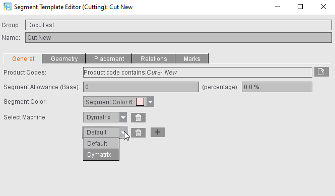
You can specify which allowances (as a base or percent) are to be expected for the segment template. These are the allowances of the appropriate reference machine.
The machines that are filed in the MDS display for a segment type (e.g. "Cutting"). You can link other machines to the template by clicking the plus button. This means that if several machines are used for the process, you do not have to create two segment templates and place them one on top of the other in the print job. Instead all the machines can be linked already with the segment template. These machine settings are also copied to the Planning Assistant in the Prinect Cockpit.
You can remove additional machines from the template again by clicking the trashcan icon.
Not only that, you can select a segment color in which the segment will display in the graphic window. You can change the default color defined for the possible segments in the Preferences (see Display color).
"Geometry" tab
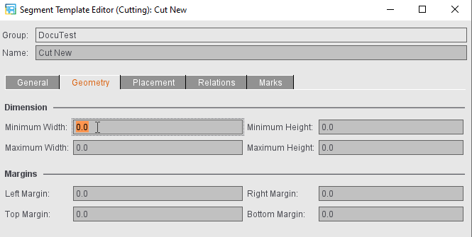
In this tab, you can select the minimum and maximum height and width of a segment.
Not only that, you can set the margins around the segment (left, right, top, bottom).
•If a margin > 0 is set in the segment template, the cut blocks of the 1ups in the segment are placed on the margin of the segment. The segment is cut on the outside.
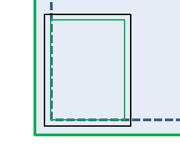
•If a margin of 0 is specified, the cut block of the content is placed directly on the cut block of the segment. The segment is cut on the inside. The outer margin of the segment arises from the margins of the content.
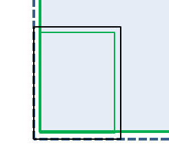
•A mixture results if the margin of the segment is smaller than the margins of the content. The segment then has an inner and an outer margin.
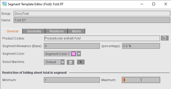
Points to note for fold segments
In the case of fold segments, the data do not refer to the press sheet but are confined to the folder.
Instead of the minimum and maximum widths and heights, you can set the minimum and maximum infeed edge and lay edge in this tab. The infeed edge of a segment is always the edge that is parallel to the first fold. The lay edge is always the edge that is perpendicular to the first fold.
Fold segments make it possible to fold one-dimensional folding sheets jointly. In some cases, the number of folding sheets to be folded jointly in a fold segment must be restricted. For that reason, for fold segments you can define the minimum and maximum number of folding sheets in the segments.
"Placement" tab (not with "Fold" type)
In the segment templates, you can define whether placement during optimization is to be oriented towards the sheet optimization setup or defined especially for this segment type. The placement specified defines the starting point of optimization.
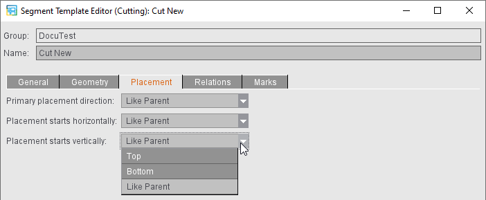
With "As top layer", the elements within this segment are placed based on the same defaults as defined for the press sheet or, in the case of segment parts, for the parent segment.
"Relations" tab
This is where you can enter allowed segment parts, in other words, which segments of a cutting segment template, for example, can follow, like a fold or finishing. In this case, it concerns only the direct successors.
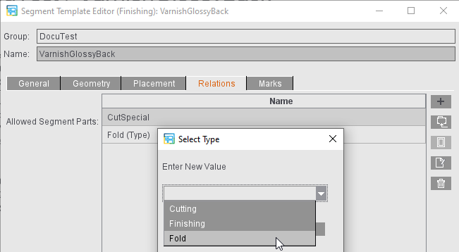
You can select the created segment templates from the file system, specify a segment type as successor or specify the name of a segment template you would like to create by entering text of your choice.
"Marks" tab
With the automatic print control marks for segments, it is possible on the one hand to add additional information to the segment and on the other the segment can be given cut marks.
The following automatic print control marks are available for segments:
•Cut Marks (for segments)
•Segment Label
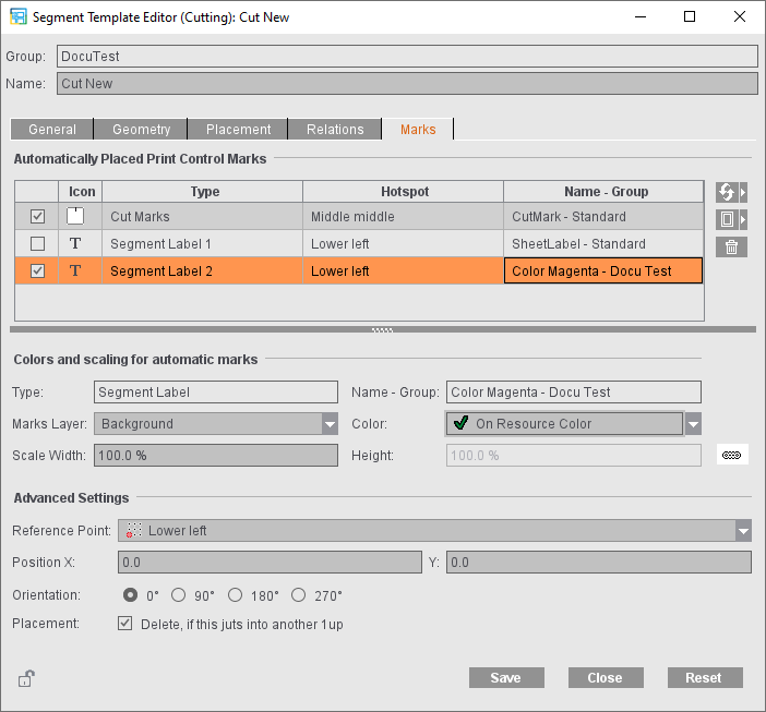
You can enable and disable cut marks (enabled by default). In addition, you can create any number of segment labels. You create these using the "Add segment label" button. Except for the first segment label, you can delete segment labels again. The first segment label is part of the standard shipment and, similar to folding sheet labels and page labels, can only be set up, enabled or disabled (disabled by default).
The following parameters are available for automatically placed cut marks for segments:
•"Color": the color layer on which the cut mark will be placed. Similar to the automatically placed print control marks in the "Marks" product part step, you can select several colors in this tab and specify those on which the marks will have a knockout effect.
•"Scaling" of the mark If the mark is to have different scaling for width and height, you can disable the proportional linking of both values using the button.
•"Marks Layer": You can place cut, fold or collating marks in the background to prevent them from covering color control bars, for example. You can select whether the mark will be printed in the foreground or background or whether it will be placed on the layer that was defined in the marks resources.
In addition, you can define the following setting for the cut mark:
•"Use Inner Marks": If the cut marks are defined as inner, they are placed on the margins, analog to the precutting marks in the Montage mode.
In addition, you can define the following settings for the segment label:
•"Reference Point": one of a total of nine points: Bottom left, Middle left, Top left, Lower middle, Middle middle, Upper middle, Bottom right, Middle right, Top right. The reference points form a grid over the segment.
•"Position": X or Y coordinate in relation to the reference point
•"Orientation": Rotation of the mark in steps of 90°: 0°, 90°, 180°, 270°
•"Placement": The segment label is deleted if it juts into a 1up of another segment.
The marks set up in the segment template are placed automatically after optimization. Cut marks that jut into other 1ups are removed. In this case, an optimized marks clip path is taken as the basis. This expects cut marks whose contents meet the standard cut mark (a line that goes from the mark center vertically to the mark height). This optimized clip path is already used for cut and fold marks on the folding sheet. Segment labels are removed only if this was set up.
You cannot edit automatically placed print control marks for segments. When selected, they have a red frame (similar to cut and fold marks of the folding sheet) instead of an orange one.