
Editors for Marks, Color Control Bars and Ink Pickup Bars
Basically, a difference is made in marks between achromatic and color marks. Achromatic marks are created with the "Marks Editor". There are separate editors for the color marks. The mark types that can be selected vary according to the editor that you invoke.
The editors have a similar structure and differ only in the settings required for a specific mark type. The basic structure of the various Marks Editors is summarized below.
"Group Name"
Displays the assigned group (folder) of the mark. You cannot edit the group name.
"Mark Name"
Displays the name of the mark. The name appears after the mark is saved to the resources. You can edit the name.
Displays the mark name in conjunction with the PPF name (alias name).
Displays the mark type; list box for setting whether the mark is a "Register Mark", "Plate Control Mark", "Scavenger Mark", "Klebrand Code Mark", "Pull Lay" and "Latestage Mark" (for text and barcode marks only).
For the "Latestage Mark" type, see Latestage Marks
Depending on which Marks Editor was started, "Color Control Mark" and/or "Ink Pickup Mark" also are available as types. The mark type you set is saved for finishing.
The two mark types, Ink Pickup Mark and Plate Control Mark, are designed for handling spot colors. More details can be found in Allow Spot Colors to BCMY.
The "PullLay" and "PullLay (fix position)" standard marks are predefined as a "Pull Lay" mark. This is necessary to identify a pull lay mark and to qualify it for transfer to the press.
"Hotspot"
A scheme or plate template has reference points. These are magnetic alignment spots that help to position the marks correctly. The hotspot of the mark snaps accurately into position above this spot. You must define the correct position of the hotspot within the mark.
If you enabled "Grid" in the graphic area, you will see that the grid has a violet hotspot.
The hotspot indicates text alignment for marks that were created with the Text Marks Editor.
"Marks Layer"
Displays the layer on which the mark is positioned; list box for setting marks to a layer, possible options: Foreground, Background
This option lets you assign a number of background colors (max. 24) to the mark. The background of the mark is colored in the background colors selected in "Job Inspector > Colors". The background color corresponds to the size of the clip path of the mark.
Prerequisite: The "Background Colors" column must be enabled in "File > Preferences > User Interface".
There may be issues if you have non-white printing material because DIPCO color control bars are always set to knockout.
•"Number of Additional Fields": You can define the number of color patches that will project beyond the subject if you have color control marks with AutoClip to subject.
There are cases where certain marks shall appear in the proof or on the printing plate only. This can be, for example, a company logo only to appear in the proof, or an ink pickup bar to be imaged on the printing plate only. Since this is usually known as early as when the mark is defined, this setting will be made in the general section of the Mark Editors
You are offered the following three options in the list:
•"Proof and printing plate": Marks will be printed in the proof and also on the printing plate
•"Proof only": The mark is printed in the proof only (without effect for direct output)
•"Printing plate only": The mark is output on the printing plate only
Assessment of the output for marks is done solely in the Prepress Manager. For this reason, the above function only applies to the Prinect workflow.
Note: The "Proof only" output is of no effect for direct output. Marks handling for direct output remains unaffected!
Display and setting of the ink coverage of a color mark for proofing. You can reduce the ink coverage of color marks, for example, to save ink when proofing.
The following requirements must be met to output marks with less ink:
•The "Proof > Print Proof Marks with Less Ink" option must be enabled in the output parameter set for the job output.
•The ink coverage of a set mark in the job must be less than 100%.
The mark can be proofed with less ink if these three requirements are met. Plate output is not affected by the reduction of ink.
•"Color": Displays the separation on which the mark is positioned; list box for defining the marks on separations.
Automatic functions
•Color Control Mark (with AutoClip)
•Color Control Mark (with AutoPositioning)

Note: The available attributes depend on which editor was started and which mark type is selected.
"Fixed position for front and back":
•The mark position in relation to the origin is generally different for front and back. For work-and-turn, for example, it is mirrored so that the mark is in the right position for the pages.
There are cases where the mark position has to be the same for the front and back. You must set this option in such cases. Barcode marks for plate identification is such a case.
"Output Mark on Paper Only"
If a mark is positioned on "paper", it is also output. If it is not, it will be suppressed.
This prevents that a mark is inadvertently scaled. When the option is set, you cannot resize the mark set in the job, neither by entering a scaling factor in the text boxes in the Marks Inspector nor by using the "Scaling" tool in the graphic window. Marks that are selected in the marks table of the Marks Inspector and assigned the "Mark Not Scalable" attribute are excluded from the set scaling and remain unchanged.

Note: You will find more details about marks for color control bars (e.g. "with AutoClip" and "with AutoPositioning") in: Color Control Bar Editor
Mirrored positioning of marks is necessary, for example, when creating plate templates for flexo plate production (coating plate).
Note: In conjunction with "Mirror mark on back", you can logically select only one or no option.
A mark is copied only to the front when it is copied to other plates.
"Clip Mark Horizontally/Vertically to Subject"

Note: At present, "Clip Mark Horizontally to Subject" and "Clip Mark Vertically to Subject" only work on non-rotated marks.
There is the option of clipping color control bars placed in relation to a press sheet to fit the subject (mark type: color control bar with AutoClip) When clipping to the subject, any color patches that would be clipped are included completely, and the color control bar is centered on the plate.
Undesired side effects can occur when this function is applied to marks not complying with the usual color control bars. On one hand, such marks are submitted to the connected measuring instruments in the CIP/PPF workflow, and on the other hand, positioning errors can occur during transfer to the back of the sheet.
This problem can be avoided with the "Clip mark to fit subject" option for easy clipping to fit the subject. This attribute is effective only for marks placed in relation to the press sheet.
The mark is clipped on the left and on the right to fit the subject when the "Clip Mark Horizontally to Subject" option is enabled. There will be no clipping at the top and at the bottom. This is necessary in order to clip ink pickup bars usually placed outside the subject to fit the subject.
When the mark contains a manually edited clip path, the path is preserved and is offset with the trim against the subject.
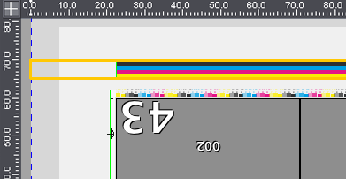
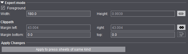
The screenshot shows an ink pickup bar with the attribute "Clip Mark Horizontally to Subject" placed on the press sheet. You can see that the mark was clipped to fit the subject. The trim is reflected in the specification for the margins in "Expert Mode / Clippath" of the Marks Inspector:

Note: If the marks are clipped only in horizontal direction, but not in vertical direction, this can make color control bars unusable because they project too far beyond the upper or lower edge of the paper. A warning where you can choose whether to cancel the output or to continue with the color control mark clipped is issued in such cases.
The mark is clipped on the top and bottom of the subject so that it does not protrude beyond the subject when "Clip Mark Vertically to Subject" is enabled.
Example: The Sensortec mark that is needed for control of the analog printing units of the Labelfire (web press with analog printing units and one digital printing unit) and must be clipped vertically so that it does not protrude into the following subject.
The mark content generally will not be mirrored if the mark position is mirrored on the back (see above).
You must only set this option if the mark content is to be mirrored on the back.

Note: In conjunction with "Mirror Mark", logically you can select only one or no option.
The background of the mark is covered the size of the clip path of the mark and as a result is not transparent.
The "Inspection Control Mark" property is set when this option is enabled.
You can use all existing marks for Inspection Control.
The "Inspection Layer" specifies the areas to be checked on the sheet, and generally, four marks are required (one at each corner of the sheet) for the "Inspection Layer" to fit the sheet exactly.
This functionality is applicable only for submission to the Prinect workflow.
No provision is made for a direct output from Signa Station.
"Do Not Check Mark During Output"
During output, a check is run to see whether a mark is within the gripper margin or out of the paper. If this is the case, a warning is issued. Some special types of marks are excluded from this warning:
•Plate Control Mark
•Pull Lay
•Print Quality Control Mark
•Scavenger Mark
Enable "Do Not Check Mark During Output" if marks that are not part of these exceptions are also not to be checked during output.
For compatibility reasons, the following marks are also excluded from the check:
•Marks with the name "PullLay"
•Marks with the name "RegisterLine"
•The "Text" mark from the "Standard" group
To select several graphic objects, hold down the Alt key and click the relevant objects with the mouse.

|
Edit tool: Edits a selected object. Click a handle with this tool to change the object. |

|
Hand tool: Moves selected objects. Click an object with this tool to move the object. |

|
Creates a circle or ellipse. |

|
Creates a straight line. |

|
Creates a square or rectangle. |

|
Colors the object below the mouse pointer black. |

|
Colors the object below the mouse pointer white. |

|
Inserts text. Enables the table for inserting placeholders. |

|
Inserts barcode object. See Barcode Properties (Barcode Object) for details |

|
Deletes selected objects. |

|
Copies selected objects. |

|
Centers selected objects. |

|
Fits canvas to bounding box. The canvas is centered in the bounding box. |

|
Brings selected objects to the front: The objects are brought to the front in the order they were selected. |

|
Zoom up graphic is set by default. A "+" appears in the magnifying glass. Hold down the "Alt" key to zoom down. A "-" appears in the magnifying glass. |
•"Grid": This option lets you display a grid and hotspot (violet circle) as a visual guide. The hotspot always appears at the center of the grid.
•"Snap lines": Snap lines are seen if you set this option. Snap lines help you position objects. In a defined area, the objects are aligned magnetically to the snap line and remain attached to it.
You can change the shape and size of the object at the snap line if you selected it with the edit cursor (e.g. a circle can become an ellipse). You can only change the object position at the snap line if you selected the object with the hand cursor.
·To create snap lines: Click the ruler with the edit tool and drag the snap line to the graphic holding down the mouse button.
·To delete snap lines: Click the snap line with the edit tool and drag it out of the graphic holding down the mouse button.
·To position snap lines: Click the snap line with the edit tool and position it holding down the mouse button.
•"Line weight": This is where you define the line weight for circles, rectangles and lines.
•List box with all the objects that are found in the graphic. You can select "All" or single objects in this box. The objects are shown in the order they were created.

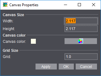
The properties dialog is context-sensitive, varying according to the object selected. The "Canvas Properties" dialog opens if an object is not selected.
If a graphic or text object is selected, the dialog that opens is "Text Properties", "Circle Properties", "Line Properties" or "Rectangle Properties", depending on what you selected.
You can select an object directly using the list box on the left. You can make changes to the objects by typing in values in the properties dialogs or also manually using the mouse pointer and a click.
The following dialogs with their options are possible:
The input options are self-explaining.
Click "OK" to apply your data and close the dialog.
Circle, Line and Rectangle Properties
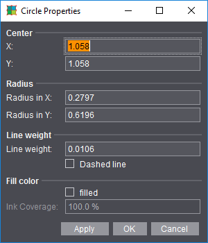
Properties
The input options for the geometric data are self-explanatory.
1.Click "OK" to apply your data and close the dialog.
2.Click "Apply" to apply your data but leave the dialog open.
3.Click "Cancel" to close the dialog without applying the values.
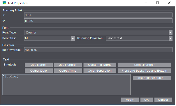
Insert the placeholders directly by clicking the buttons beside Shortcuts or select others with "Insert placeholder...". More details can be found in Insert placeholder .
Click "OK" to apply your data and close the dialog.
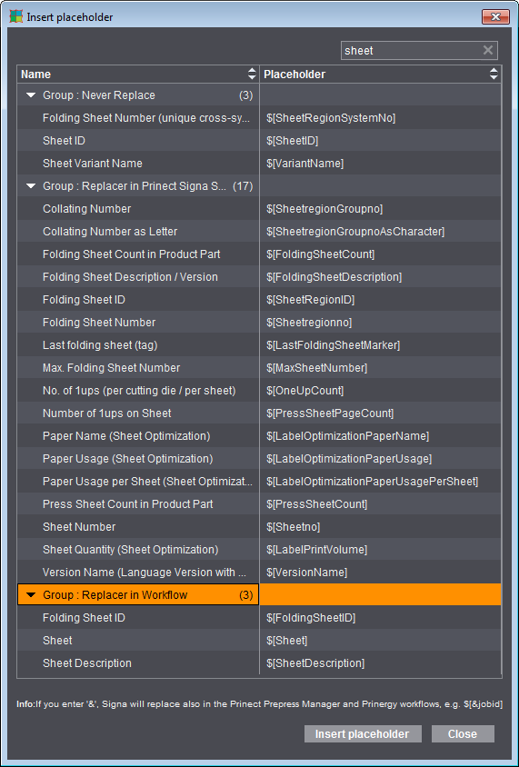
Grouping Table
The grouping table shows an overview of the placeholders by replacement mode.
1.Click the arrow on the left to open the group.
You can also sort the table by name and placeholder.
2.Click the "up" and "down" arrows in the respective column.
3.You can insert a placeholder either by double-clicking its name or by selecting it and then clicking "Insert placeholder".
To exit the table:
4.Quit the table by clicking "Close".
Filter
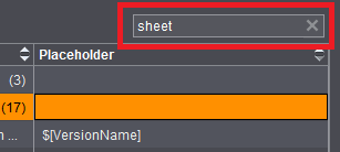
You can type in a filter criterion in the search box to the right above the table. In the filtering process, the text is looked for in both columns (Name and Placeholder) and the rows filtered accordingly. Uppercase and lowercase are not important. Placeholders that do not have the search text neither in the name nor in the placeholder itself are filtered out and consequently do not display in the table. The filter is revoked by removing the filter criterion from the text box or by clicking the 'x'.
Barcode Properties (Barcode Object)
If you selected the "Barcode Object" tool, the "Barcode Properties" dialog opens after you clicked the canvas to let you define all the properties of the mark. The settings that are possible are equivalent to those in the Barcode Editor. In addition, you can define the starting point (bottom left corner of the barcode) on the canvas analog to the other graphic objects. When the dialog opens, the position on the canvas is indicated which was clicked when creating the barcode. The barcode object lets you define several (similar and different) barcodes within one mark. In this way, for example, you can create ASIR marks where the barcode must be placed three times one after the other without needing the "IDAutomation" font for it.
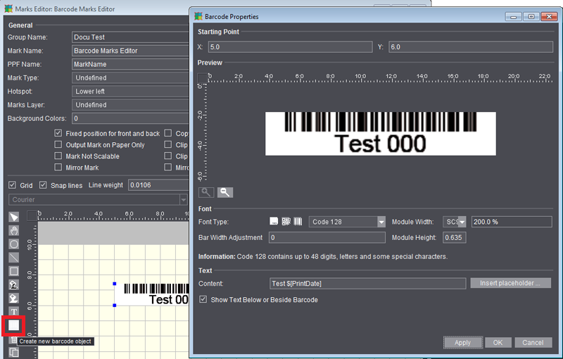
For a description of the barcode properties, see Barcode Editor
Loading the 'Marks' Resource to the Job
The marks are also loaded indirectly with the "Plate Templates" resource. On the plate template, the marks set refer to the plate, paper or subject.
This is where you load the "Marks" resource to the job:
•"Marks" step > enable "Automatically Placed Print Control Marks". The cut marks and folding sheet labels that are set relate to the pages or folding sheet, and the folding and collating marks to the folding sheet. The marks are selected in the preferences.
•Folding Sheet Inspector > "Marks" / "Marks Resources"
•Press Sheet Inspector > "Marks" / "Marks Resources"
•Page Inspector > "Marks" / "Marks Resources"
•Direct assignment by dragging and dropping the resource from the "Marks Resources" tab of the inspectors named above.