You can save the job data as a template. Do this in the Browser window by displaying the context menu and selecting "Save job as 'Resources/Job Templates'". You can then display this job again with "Job from Template" or list it in "Resources > Job Templates". The job template contains all the Signa Station job data, except for the job number, job name, customer name and customer ID.
The job name is based on the "Job Number" and "Job Name" boxes.
Job Number
The job number is used in finishing, among other things in the JDF workflow with the Prepress Manager, and by default is part of the full job name. It can be made up of alphanumeric characters, e.g. "49rs".
Job Name
Is used to spot a job easily and by default is part of the full job name, e.g. "labelsSM102".
Customer Name
Is also used to spot a job and can be a default part of the full job name.
Details about the customer. You can save customer data as a template and call them up again when required.
•Folder button
You can save a customer as a template in the resources and use this button to display it again.
Customer ID
Additional customer code (e.g. customer ID). The customer ID can be a default part of the full job name.
•Info box
Details about the customer.
The full job name is made up of default placeholders and the general file extension ".sdf". In "File > Preferences > Names > Job File Name", the default is generally:
Jobid, jobname
The following full job name is generated automatically if you enter "01" in "Job Number" and "Smith" in "Job Name":
"01_Smith.sdf"
Note: To change the default, select the placeholder you want. Go to "File > Preferences > Names", in "Job File Name" select the placeholders you want. See Job File Name.
Details about the target date, number of copies, number of layers and planned colors.
There is also an enhanced versioning option: If you select more than one layer, you can use the many enhanced options in "Versions". More details can be found below in Basics of the Workflow Bar and in Working with Versions.
You can set the "target date" using a calendar that you display by clicking the arrow on the right. Click the arrow again to quit the calendar without changing the date.
In certain cases, PDF documents must be placed on different layers so that they can be printed one on top of the other in a job, for example, if it has several languages. The list box to the right will be enabled, and the layers displayed if you enter more than one layer.
You can now change a layer name in this box, e.g. by entering the language. You can output this name on the press sheet using a text mark. A maximum of 201 layers can be used.
You can assign the layers certain names in "Preferences > Names" that can then be used as default layer names when you enter several layers in the "Job" step. You can, however, change them at any time. You will find more details about working with several layers in Default Layer Names .
Use the button to invoke the "Layer Name Editor" where you can customize the layer and level names for a specific job.
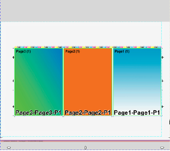
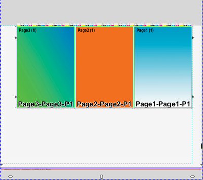
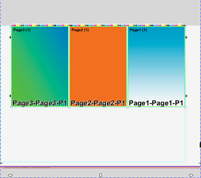
Example for a bilingual document (= 3 layers, 2 versions):
|
Layers |
Level |
|---|---|
|
Images |
Basic |
|
German |
Text |
|
English |
Text |
"Level" is an additional identifier (e.g. color, black-and-white or base, text) of the content of a layer. However, it is not mandatory to enter it.
Layers with the same content must have a unique (identical) level name.
The "Level" parameter is submitted in the JDF workflow and, for example, allows proofing of the level in question.
The following description should help you decide whether you will work with the new versioning or whether you will use the "old" layer versioning:
•Layers = 1, versions = 0: Work is without versions and layers
•Layers >1, versions = 0: Work is with layers but without versions (= old versioning)
•Layers >1, versions = 1: Single version
One version containing all the configured layers is set up. The version name is automatically derived from the existing layer names. Version name and assigned layers cannot be changed.
•Layers >1, versions >1 (one less than layers): Version names and assigned layers can be edited.
•A single version is created automatically for jobs with segmented folding sheets ("Master Pages" step > "Segmented Folding Sheets").
The number you enter for versions depends on the "Number of Layers" box. You can enter versions only if more than one layer is set. The maximum number of versions is equal to the number of layers minus 1. The upper limit for layers is 201, and 200 for versions with 201 layers. If you enter a higher value, Signa Station automatically replaces the value by the maximum value possible.

Note: You can specify "Press sheet variants" in the "Plates" step if "Number of Layers" is greater than '1' and "Versions" is at least '1'.
New versioning:
The combination of "layers" and "versions" gives you a wide range of options. Click the button on the right beside the option chooser. The "Version Editor" opens.
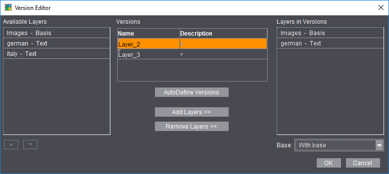
You will see the defined "layers" in the left column. The middle column shows the defined versions (it does not have to be a language version). The right column shows the selected combination of layers in a version.
After you mark a version, you can then assign the layers you want to the version, or you can let them be assigned automatically.
If you set "Without Base" in the "Base" list box function, the base layer is removed from all existing versions, "AutoDefine Versions" creates versions with a base layer. "Defaults" in the Signa Station Preferences define whether the versions are by default created with or without a base layer (see Create Versions with Base Layer).
You can also create additional base layers by defining, for example, 6 layers with 4 versions and by then renaming a layer to a base layer. This lets you assign other base layers specifically to certain versions. Make sure that these additionally defined base layers are in the left list in the editor above the assigned (text) layers because the list determines the order of printing. If required, you can change the order in the list using the arrow buttons or with drag-and-drop. Only the first base layer cannot be moved.

Note: You can also set a "Description" of the version in the middle column beside the version "Name". This description is sent to Cockpit.
When this check box is enabled, the active job is saved and its current, implemented resources are frozen.
When you open the job later, the obligatory question of "Update resources..." would not appear and there is no update.
This setting can be useful for repeat jobs in order to base your work on the original resources.
Default for JDF and job ticket (third-party workflow)
This option lets you define how many colors will be used in printing when you create layouts in "JT" or "JDF". For a PDF marks layer, the combi mark that matches the colors set here is then used.
It only makes sense to define colors if no content pages were positioned. If they were, the colors set for the content pages are used during output.
This box allows you to enter additional information about a job. You can define the note as a text mark placeholder. This allows you to position and print it out. See Creating a Text Mark.
As an option, you can view the notes each time the file opens.
Created on/Modified on
Signa Station shows the dates in these boxes. You cannot change them.
•Info box
Displays all the details about the job history.
Created by/Modified by
The name of the user logged in to Signa Station appears automatically in this box. You cannot change the name afterwards.
It is possible to set spot colors to the "BCMY" process color code when this option is enabled. By doing this, you can avoid gaps in the color control bar.
Default: The option is set by default for new jobs, it is disabled by default for existing jobs (older than version 4.5).
Issues arose in the HEIDELBERG workflow due to a rigid order of colors if a job did not have all the process colors but spot colors as substitutes or even only had spot colors.
Now it is possible that color mapping is done automatically by Signa Station. In this process, the spot colors are mapped to the BCMY placeholders.
Use Global Mark Color Mappings
"Global Mark Color Mappings" is disabled by default when you create a new job.
When this option is disabled, color mapping of all the press sheets with the relevant surfaces (front and back) is done in the Press Sheet Inspector.
When the option is enabled, color mapping can be done for the entire job, either automatically or manually. In this case, you cannot use the function in the Press Sheet Inspector.
Automatic Color Mapping
"Automatic Color Mapping" is the default setting. The system automatically tries to avoid gaps in the color control bar.
The "User-defined Color Mapping" window displays. You can now set all separation colors manually to marks color placeholders of the HD alphabet. Click the "In mark" code and select the link you want.
We recommend that you use "Automatic Color Mapping" in the workflow.
Display of the available colors in tables
Display the colors available in the product part as color boxes.
Colors that are in the PDF pages assigned to the product part.
Click an element in this column to display the output options for spot colors. This parameter lets you replace spot colors by C, M, Y or K or by another spot color in the PDF document and print them. In this way, for example, you can replace similar looking spot colors by another color, thus saving ink/inking units. Other options:
As a visual aid, the new color box inserted at the beginning of the row changes according to what you select.
•as process colors
The spot color is converted to the process colors C, M, Y and/or K that are written and printed to the plates.
•is ignored
The spot color or process color is removed from the list and not printed.
•To color
You can map the spot color to a process color.
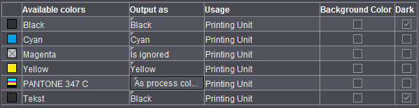
Only if "Column for Usage" is enabled in "File > Preferences > User Interface".
You can disable spot colors in marks manually. The spot color is ignored in color control bars in combi marks and also in the workflow with "Allow Spot Colors to BCMY".
The table below shows you the handling options:
|
Cases |
Rule |
Description |
Usage |
Ink Code / Order |
|---|---|---|---|---|
|
1 |
Color code from |
Color is assigned a code from "HD alphabet", included in the color bar |
Printing Unit |
Yes/Yes |
|
2 |
Color code from |
Color is assigned a code from "HD alphabet", ignored in the color bar |
Printing Unit, No Color Control |
Yes/No |
|
3 |
Color code L1-L4, not in color control bar |
Color is assigned a code from L1 - L4, ignored in the color bar |
Coating Unit |
Yes/No |
|
4 |
No color code |
No color code is assigned |
Proofing, tool, other |
No/No |
Dark
Only if "Column for Darkest Color" is enabled in "File > Preferences > User Interface". See Column for Background Colors.
Background colors
Only if "Column for Background Colors" is enabled in "File > Preferences > User Interface". This is where you can define which colors will be the background colors.
"Background colors" are evaluated in the "Prinect Cockpit (via JDF)" output variant. The maximum number of background colors wanted in the Prepress Manager are entered. You must enable this number also in the color marks used.
Details can also be found in the Marks Editor in "Background Colors".
Default Screen Angles for RIPs
Settings in this group do not affect the HEIDELBERG workflow. The values are used only when you output to third-party RIPs.
You can define the screen angle manually for each single color in the color table that then appears (may be necessary for some third-party workflows).
To change a color, click the "Angle" column and key in the value you want.
The modified screen angle is taken into account during output.
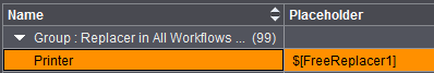
You can define specific job attributes in "File > Preferences > Names". These display in this group and can be filled with job-specific data. See Free Text Replacer Names.
Procedure:
Create a text mark with the Text Mark Editor, add, for example, "FreeReplacer 1" or the name entered in "File > Preferences > Names" ("printer") as the placeholder. The relevant variable then appears, in our example "$[FreeReplacer1]".
After you save the text mark, position it, for example, on the folding sheet.
After you positioned the text mark, you can change the placeholder text at any time in "Attributes" in the "Job" step. Simply type in your text that then automatically appears immediately in the text mark. You can check the modified text at once in the graphic window.
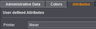
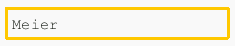
This means that you can change the text of a text mark at any time without having to first position a new mark.
In the "Product Part" step, you define the work mode that you need for your product part or you can select a template from the resources with Product Part from Template. The following work modes are available: Imposition, Automatic Imposition, Montage, Packaging and Ganging Optimization (gang job).
Only the steps that you need for the work mode you selected display in the workflow bar.
Five more product part steps appear when you select "Imposition" or "Automatic Imposition": "Master Pages", "Binding", "Marks", "Plates" and "Schemes".
Another product part step, "Assembly Block", appears when you select "Montage".
Another two product part steps, "Packaging" and "Article", appear when you select "Packaging".
Another two product part steps, "Optimization" and "Results", appear when you select "Ganging Optimization". In addition, you can select "Sheet Optimization without Layout Default" and "Sheet Optimization with Layout Default". Select "Sheet Optimization for Packaging" for a packaging job.

Note: Individual changes you made to a product part with other inspectors (e.g. folding sheet offset with the Press Sheet Inspector) can be lost if you modify this product part in the "Product Part" step! You should give much thought to how you will create a product part, and only make changes to single objects in the product part when you are sure that you don't have to make any further inputs/changes in the "Product Part" step.
You can manually lock or unlock the currently displayed product part.
In the Preferences, you can set that the product part will be locked automatically after changes are made to an item in it. See Automatic lock for Product Part Inspector for details.
When a product part is locked, you can only make minor changes to it in the "Imposition" and "Montage" work modes (e.g. set automatic cut marks). You cannot use other functions that require the job data to be recalculated.
During a recalculation, some of the manual changes to certain items (in the Folding Sheet and Press Sheet Inspectors) are overwritten. Because this is not always wanted, customers requested that the appropriate functions in the product part are disabled by a lock.
The header of the product part steps indicates the locked status by a yellow padlock:
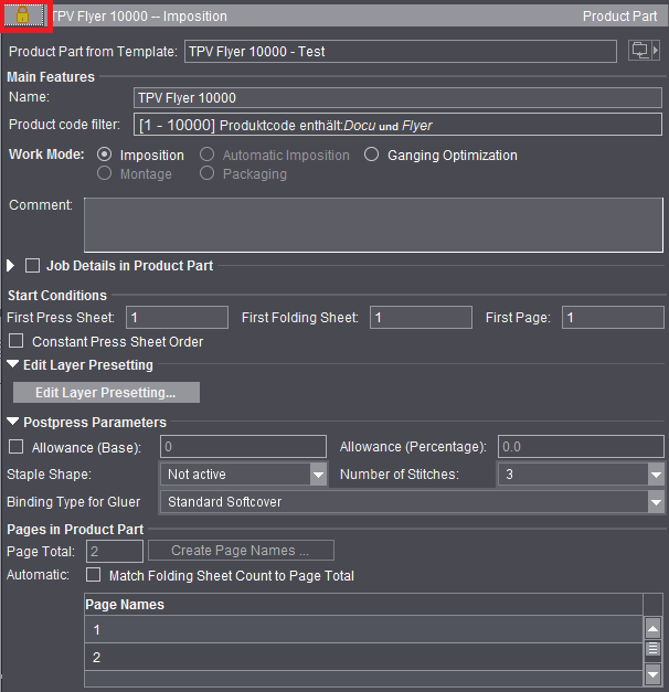
Product part status: locked
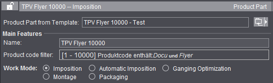
Product part status: not locked
The top screenshot shows the "locked" status. The "Product Part from Template", "Work Mode" and "Pages in Product Part" functions are disabled accordingly. Functions affected in the other steps are also disabled.
You can change the status manually at any time with a click on the lock. This lets you use all the functions again.
You can save the product part as a template. Do this in the Browser window by displaying the context menu and selecting "Save product part as 'Resources/Product Part Templates'". You can then display this product part again as a template (by clicking the folder button on the right) or list it in "Resources > Product Part Templates". The product part template contains all the Signa Station product part data without data pages. The administrative data of the job are not part of the product part. See also the Job (Administrative Data) .
Use product part templates for MIS import
When a job in JDF format is imported (MIS import), a large part of the layout generally has to be retouched because the layout definition in the MIS JDF is not very accurate. For recurring jobs (default jobs) that only differ in the number of pages, the "Product Part from Template" function in combination with "Match Folding Sheet Count to Page Total" makes it possible for you to give such jobs the required layout fast.
Create the product part template with the Product Part Template Editor so that it contains all possible plate templates ("Plates" step) and one copy each of all possible folding sheets ("Schemes" step). The "Page Total" in the "Product Part" step results from this: For example, you must enter 4+8+16=28 if folding sheet types 4, 8 and 16 are needed. In addition, "Match Folding Sheet Count to Page Total" must be enabled in the "Product Part" step. For the rest of the product part, create it so that it is suited for the production of the default job.
When you import the default job, select the product part template created for it using "Product Part from Template". The selected product part with all its attributes is enabled and the number of pages in the MIS job is applied to it. This means that press sheets/folding sheets in the template are duplicated or removed to match the page total. All parameters in the template like folding sheet positions, cutting data, creeping, etc are retained. The header data (customer, job number, etc.) and paper data from the MIS job are retained.
You can type/change the name of the selected product part in this box.
Shows the production type (= product code) entered in the product part.
This information makes it possible for the required product part to be used automatically in the "Gang Job" and "SignaServer" workflows. More details are to be found in the description in the Types of Gang Jobs and Their Editing section.
In addition to the keywords for production type, it is also possible for you to use the delivery quantity for selection of the product part.
In the current job, the product code filter that displays is for your information only and cannot be edited. You can invoke the editor for creating the product code filter in the "Product Part" step when you are editing the product part template.
More details can be found in Product Code Filter Editor.
You can define a number of keywords for the product code, but only once the delivery quantity threshold as of which this product part will be used.
Example:
2 product part templates ("Broschure -200" and "Broschure 201-") have been created.
One of them is to be used for brochures up to a quantity of 200 for printing on the digital press.
The second product part template is to be used for brochures with a quantity of more than 200 for printing on an offset press.
An XML could look as follows:
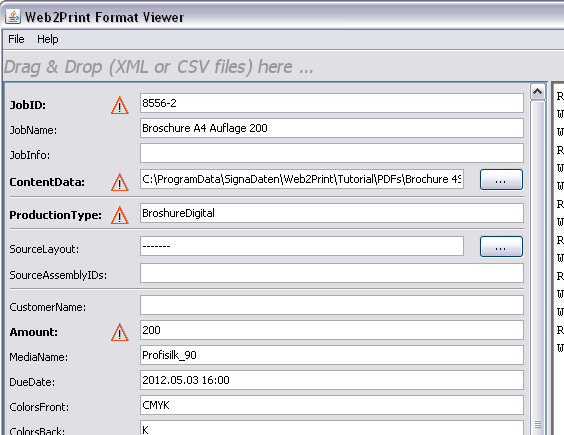
"BrochureDigital" is specified here as "Production Type". There is no such production type. But there are two types with "Brochure*".
One with a delivery quantity of up to and including 200. This type is found because the XML requires a delivery quantity of 200 in "Amount".
The second product part template is used if the delivery quantity is 201 or more.
The work mode you select defines the structure of a product part. The content of a job is shaped by what or how many work modes you selected. A job can have different work modes (product parts).
A certain number of pages are imposed based on a folding scheme you selected. You only create as many sheets as you need for the number of pages. You define the number of pages in "Page Total". In contrast to automatic imposition, no sheets are added or removed automatically.
In this mode, you can process different folding schemes and paper and plate templates in one job.
This is important, for example, if the page total cannot be processed with one folding scheme (20 pages can be imposed with a 16 folding scheme and a 4 folding scheme).

Note: Changing the page total subsequently does not mean that the number of sheets are automatically matched to this total. The user must change this manually.
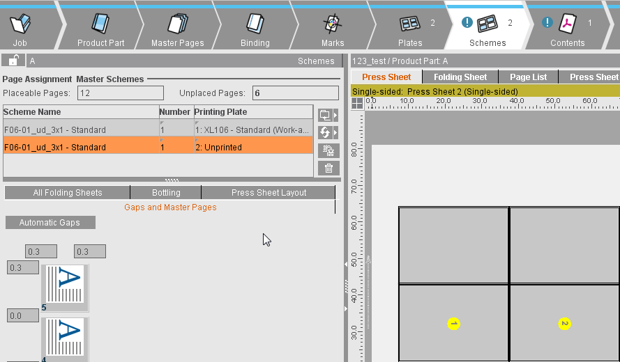
You can change the number of sheets in the "Schemes" step in "Number" in the table so that the value shown in "Unplaced Pages" is "0". You can also add another, suitable scheme for the "unplaced pages" using the folder button.
You can also change the names of single pages, for example, to make it easier to tell the cover of a job from the body. This makes it much easier in some documents to place single data pages correctly on the press sheet. To do this, you must select the row with the page you want or a page range and then choose "Change Page Names" in the context menu.
A consecutive number is automatically added to the page name you entered (I becomes I1, I2, I3, ...) if you selected several pages. If the page name you entered is a digit, consecutive numbers are generated as page names starting with this number (32 becomes 32, 33, 34, ...).
Different folding sheets can be placed on the plate template if you enabled the "Gang run form" option (in the "Plates" step).
In this work mode, an undefined number of pages are imposed automatically based on the folding scheme you selected. You do not have to define a set number of pages. The required number of press sheets is created automatically (duplicates of the first sheet) when you assign data pages later. In this mode, it's not possible to combine different folding schemes.
You can use this mode, for example, if you wish to assign documents with a large number of pages to a layout in the Prepress Manager. The processing of books in particular is a typical case for an automated workflow.
Ganging Optimization (gang job)
Enable this option to process jobs automatically with the special "Gang Job" workflow. The workflow bar changes accordingly. You can set other options in "Sheet Optimization". See Introduction to a Gang Job with Sheet Optimi-zation for a description of working with gang jobs.
In this work mode, pages are not imposed on the basis of a selected folding scheme, but single pages, also known as 1ups, are created in assembly blocks/sheets.
In this mode, Signa Station assumes that only one sheet will be needed for the assembly. An example here would be a large-format film. You can fill this sheet with 1ups of the pages or place the pages freely on the sheet by dragging-and-dropping them there.
This work mode is very suited for the production of postcards, business cards or labels.
The option is only available if you have a license for "Packaging Pro" and/or "Label Pro". Details about packaging are found in Packaging (Packaging Pro, Label Pro).
When you create a gang job, select the "Ganging Optimization" work mode with the "Sheet Optimization for Packaging" option. See Ways of Working with Gang Jobs.
Comment
It's a good idea to comment the special features of a product part if you wish to use it as a template.
These settings are available only in the "Ganging Optimization" mode. See Introduction to a Gang Job with Sheet Optimi-zation.
These settings are available only in the "Ganging Optimization" mode.
When manually creating a gang run form on Signa Station and also during automatic processing by the Signa Station Gang Server, you can enter product codes and create a layout directly in a Prinect job.
During automatic processing by the Signa Station Gang Server, various functions are triggered by the use of product codes in the workflow:
•Job creation with matching process network via Smart Automation
•Automatic start of processing
•Definition of the procedure instructions for the matching gang run form based on placed gang parts
In order for the layout to be sent to Prinect, a suitable output parameter set must be selected. The output folder must be accessible for the Prinect system.
The following specifications apply:
•Creation of a Prinect job "in the Business Manager" only allows output parameter sets that have "Prinect 21(via Prinect Business Manager)" set as the output variant.
This is applicable both for Signa Station (in the product part) and for the Signa Gang Server (in the task).
•Creation of a Prinect job "in the Integration Manager" does not allow any output parameter sets that have "Prinect 21(via Prinect Business Manager)" set as the output variant.
This is applicable both for Signa Station (in the product part) and for the Signa Gang Server (in the task).
•Consequently, an output parameter set with "Prinect 21(via Prinect Business Manager)" as the output variant is allowed only when "Create Prinect Job in the Business Manager" is enabled.
Before printing to the output folder, you will be asked whether the layout will be used in the Prinect job. A message displays the import folder in the Prinect system if the layout was sent error-free to the system.
|
Field Name |
Description |
|---|---|
|
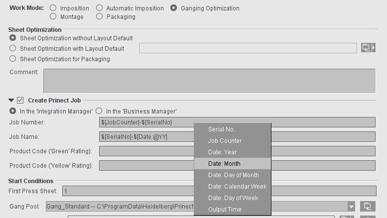
In the Integration Manager/In the Business Manager |
This is where you select whether the job will be created in Integration Manager or in Business Manager. When your selection is used in a product part template and automatic processing via gang tasks, make sure that the settings from the product part have an impact only if "Job Data from Template" is enabled in the gang task. Note: If the job is to be created in Business Manager, the job number is always defined in Business Manager. As a result, the "Job Number" box is dimmed here in the settings in Signa Station. |
|
Job ID / Job Name |
Number and name of the job as it will be created in Cockpit. The following differentiation is possible with the "SerialNo" placeholder: For example, if a task processed on day X is restarted manually on the same day, the data are written to a new job with the serial number placeholder. If a serial number placeholder is not used, a second job is not created and the data of the second run are added to the existing job. The "next run" resulting from these settings then displays in the properties list and is always up-to-date for each task in the "Planned Tasks" window. You must fill out both boxes. If not, an error message will be issued when going to a different step. During the first import to the input list in "Optimization", any placeholders will be replaced and you can then no longer edit the "Job Number/Job Name" boxes. |
|
Product Code |
You can use these boxes to define product codes based on which the gang jobs will either be automatically processed further by Cockpit ("green" rating) or stopped for manual correction ("yellow" rating). The product codes you set in these boxes are entered in the layout JDF. Nothing is entered in the layout JDF if a product code is not defined. The "'green' rating" product code is entered if the "'yellow' rating" product code is not defined. |
The data for job number and job name as well as the product codes are defined in the product part template. There are two option when processing:
•When you are working with the Signa Station Gang Server, the data are taken from the assigned product part template ("Job Data from Template" enabled in the gang task and product part template selected in "Template").
•The job data are set in the gang task ("Job Data from Task" and boxes for job number/name and, if necessary, product codes filled out). This is advisable if various gang tasks use the same template.
You can hide the function using "File > Preferences > User Interface".
When this function is enabled, you can name specific job details for each product part in a job with several product parts.
Active versions in product part (only with version cluster)
This table shows you all created versions plus a description of each if you have a version cluster (= several product parts).
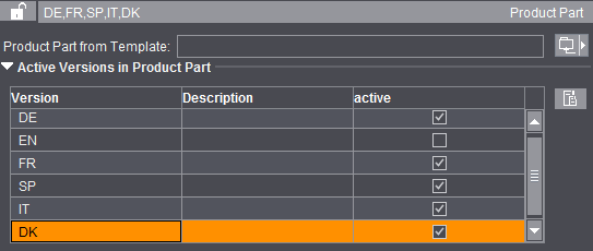
The check box in the "active" column lets you assign the versions you want to the selected product part. A version that is already found in another product part of this version cluster is removed from this product part when you assign it to a selected product part.
You go to the "Product Part" step to process the version cluster using the button to the right of the list.
First Press Sheet
In automatic press sheet generation, you can change the starting number of the first press sheet manually. All following press sheets are incremented accordingly.
Defines the start of the first press sheet in a product part. Enter "5" if you want the number of the first press sheet in the product part to be a five (can be seen immediately in the graphic window and is part of the sheet label in output).
First Folding Sheet
This defines the number of the first folding sheet in the product part. The folding sheet number affects calculation of the collating marks (starting position) and the folding sheet label.
First page
You can change the number of the first page. Page numbers and page name are affected by this.
Gang Pool (only in the "Ganging Optimization" mode).
This is where you set a job-specific folder from which the gang parts will be imported during a gang job. The content of this folder then displays when the "Job Import from Gang Pool" window opens. The default folder for the gang pool is the one that is set in "Ganging Optimization > Default for Gang Pool" in the "Preferences".
If multiple gang pools are defined in Preferences, the first one in the list will be selected by default.
If a different folder is set for the job, the display is refreshed in the "Job Import from Gang Pool" window even if the window is already open. The path to the folder set in the job is saved along with the document, meaning that the job-specific folder displays again when the job is reopened.
If the default is used, this setting is also kept in the job even if the preferences should have changed when the job is next opened.

Note: You cannot change the folder in the "Job Import from Gang Pool" window as long as the job is open; the folder set in the job always displays in this window.
Filter for gang jobs (only in the "Ganging Optimization" mode)
In the product part, you can already define the filter settings with which the "Job Import from Gang Pool" window opens and the jobs to which the view of the gang pool is to be restricted when you click on "Ganging" or invoke it via the "Tools" menu.
This is also possible when creating a product part template via the Product Part Template Editor. This way, the filter setting is already applied to the job when the product part template is selected, making it unnecessary to select it manually each time in the job in the "Job Import from Gang Pool" window.
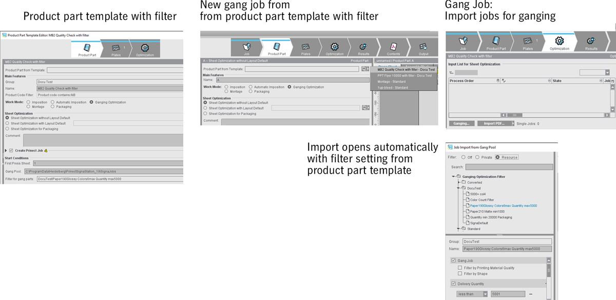
The filter is only a presetting; you can select another filter or edit the filter in the specific job. Selecting another filter will not affect the product part template. The selection will only be retained if the dialog is invoked for this job.
A change to the filter settings can be exported to the resources by clicking "Save"; thus, it applies to all future jobs using this filter or a product part template with this filter.
Even with automatic ganging, a product part template with filter definition can be used for the ganging task and set so that the filter of the product part template is used ("From Template" option, see Ganging Optimization Task Editor).

Note: Only in the "Ganging Optimization" work mode with "Sheet Optimization without Layout Default" and "Sheet Optimization for Packaging" (here only "Template for CAD Assembly Block" can be selected).
This is where you can set the templates that will be used as defaults for the assembly block or CAD assembled block during ganging optimization as well as the product codes that will be used in each case as the default during sheet optimization with segments. To select a template, click the right folder button. You can select only product parts of the "Montage" work mode. The default templates are those that are set in "Ganging Optimization > Default for Sheet Optimization" in the "Preferences".
Default for Product Codes Search

Note: Only in the "Ganging Optimization" work mode with "Sheet Optimization without Layout Default" and "Sheet Optimization for Packaging".
When working with ganging optimization, the gang parts for this gang job are scanned for product codes in the product part template group set in this box. The default group is the one that is set in "Ganging Optimization > Default for Product Codes Search" in the "Preferences".
Like the gang pool, this setting is also saved along with the job. As a result, the original product part template group is kept when the job is reopened even if the preferences were changed in the meantime.
You can hide the function using "File > Preferences > User Interface".
You can select and edit preferences for the saddlestitcher (staple shape and number of staples).
"Allowance (Base)" and "Allowance (Percentage)" are new parameters for sheet optimization. The optimization algorithm needs details about the allowance for cutting and folding.
Allowance (Base)
Fixed portion of the allowance for automatic calculation of the allowance in sheet optimization. More details can be found in Sheet Optimizations.
Allowance (Percentage)
Percentage of the allowance depending on production quantity for automatic calculation of the allowance in sheet optimization. More details can be found in Sheet Optimizations.
Staple Shape
List box with different staple shapes for the saddlestitcher. The parameters from the output parameter set are applicable if "not active" is set (for a schematic representation of the staple shapes, see Saddlestitcher).
Number of Stitches
List box with the number of staples for the saddlestitcher.
Binding Type for Gluer
The value is written to the output JDF and can be used in postpress for machine presetting. The setting has no impact in Signa Station.
This is a workflow option for quota jobs (jobs with part shipments/versions).
A quota job is generally created in Business Manager. A JDF file that is loaded in Signa Station is created. A product part template is used or selected by means of a default product code and is then used for creating a layout.
These are always jobs with versions. The quantity and the names of the versions are provided by the JDF file. However, this file does not have any information about the layers in the versions and their levels.
To provide this information, you can now predefine layers and levels in the product part. These will be used if you are going to create a layout for a quota job.
The editor for creating and editing layers opens.
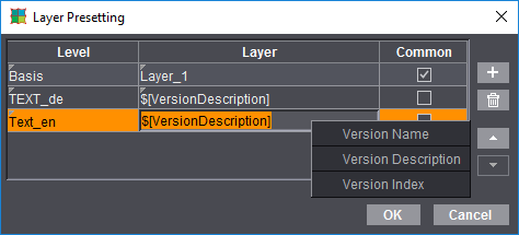
The number of rows is equivalent to the number of layers that will be in the versions you will create.
The following data are necessary:
•Level: The level the layer belongs to.
•Layer: The name of the layer you will create. A layer must have a placeholder for levels that are not to be identical for all versions. If it hasn't one, you cannot create different layer names for different versions. The following placeholders are available:
·$[VersionNameSimple] - The name of the version that is specified in the JDF
·$[VersionDescription] - The description of the version from the JDF
·$[VersionIndex] - The index of the version in the list of versions
·$[PageCount]
For layers that are shared by all versions of a specific page length. If a new product job is generated based on such a product part template with a page count-dependent layer, then the $[PageCount] placeholder is replaced by the page count that is in the version.
•Common: Indicates whether the set level is to be identical for all versions.
You can add placeholders in the layer names using the context menu.
Prerequisites:
•All levels and layers must be defined.
•The names of levels and layers must be different.
•There must be no placeholder in a layer name if the layer is defined as a common layer. A layer must have a placeholder in its name if it is not defined as a common layer.
Pages in Product Part / Page Names (in the 'Imposition' mode only)
Input of the number of pages in the open product part.
Page Total / Create Page Names ...
You can find a general description of "Page Total" in the description of the "Imposition" work mode (see Imposition).
"Create Page Names ..."
Implemented automated mechanisms in the function facilitate the input of page names, especially if there are several language versions.
Automatic: Match Folding Sheet Count to Page Total
If this option is set, the folding sheets are matched automatically to a page total that was modified.
The following prerequisites for this function must be met:
•You must obtain the required number of pages by duplicating or deleting existing folding sheets. An error message is issued if this is not the case.
•Each folding sheet type (4, 8, 16,...) may be only once in the product part template, exception: If "First Folding Sheet is Cover" is set in the product part, then there can be two folding sheets of the same type.
•The folding sheets may not have any customized changes as changes would be lost in the Folding Sheet Inspector or Press Sheet Inspector.
Procedure without product part template
1.Start the workflow bar with "File > New". Click the "Product Part" step.
2.Specify a normal number of pages in "Page Total" and enable the "Match Folding Sheet Count to Page Total" option.
3.Select, for example, three different folding schemes in the "Schemes" step. Schemes of 4, 8 and 16 are good choices:
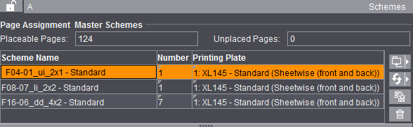
4.In the "Product Part" step, you can now increase or decrease the page total by the amount required. In the Browser window in "Folding Sheets" or in the graphic window > "Press Sheet List", you can view how your number of folding sheets are matched automatically:
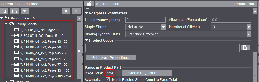
On the left, you see the number of folding sheets for a page total of 124.
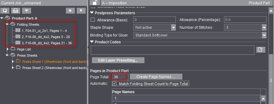
On the left, you see the number of folding sheets for a page total of 36.
Automatically placed print control marks
In the "Montage" or "Packaging" work mode, you can have print control marks placed automatically in the "Marks" step like with imposition jobs. By default, the fields are populated with those marks that were defined in "Resources" in the Preferences. You can select any mark you wish when you click the folder button. Specify a different percentage to change the scale factor of the mark. With the list box, you can specify the color layers to which the mark is to be applied.
•Cut Marks (enabled by default only in the "Montage" mode)
•1up ID
The automatic mark was designed mainly to identify 1ups on a gang job. The mark shows the job ID and sheet number on the "ProofColor" layer and knocks out the background.
You can also use the function in the "Montage" and "Packaging" modes.
"Master Pages" contain data about the page formats for the "Imposition" or "Automatic Imposition" work modes.
This is where you can define the trimmed size, the trim, the page size for special master pages and the position of the page content for every master page. You can also define whether just one master page, two master pages or special master pages will be used in the product part. The values apply to all the pages of the product part.
Master Page Types and Trimmed Size
Types
In this list box, you can select whether you need one or more master pages in the product part. You will only need one page type if all the pages in the job have the same trimmed size and if the user data (PDF pages) that will be assigned later have a similar structure. In other words, that they can be handled the same when they are being positioned within the master page. In this case, the "Current Type" list box is dimmed.
Select "Left pages" if the user data (PDF pages) can have different positions for the right and left pages. You now can specify the values for this page. Now select "Right Pages". Except for the placement rule, the values for the left page also apply to the right page.
This may be necessary, for example, if different positions for a left and right page were assigned and there is no trim box in the PDF document.

Note: Only one page type must be created if the PDF document has a trim box because contents/pages with different positions are automatically aligned using the trim box. You can view the trim box of the PDF documents in the Document Inspector and, if necessary, correct it there.
Select "Custom" if a folding scheme has different formats, e.g. a letterfold with shorter pages. The display/input options below are then enabled. You can also define any number of master pages, the special master pages. This allows you to use different formats in a scheme. You can assign a special master page to a page in the scheme either in the Folding Sheet Inspector > Scheme display or in the "Schemes" step > Gaps and Master Pages. The page then has a green page number.
A case where you would use a special master page is with a larger page in an advertising leaflet or with fold-out pages in a magazine.
To override the automatic bleed:
There are special cases where a bleed must jut into the adjacent page. You can allow this by creating a special master page with a custom bleed because the automatic bleed cannot be applied to special master pages.
In addition, you can disable "AutoReduce Bleed" in the Page/1up Inspector.
Setup of a special master page
Click the "+" icon to display a dialog where you can enter a name for the special master page. The values shown or modified below it then apply to the special master page with this name.
You can click the folder button and select an existing format from the resources. The name is then automatically used for the special master page.
You can delete the displayed special master page and its values from the list by clicking the trashcan icon.
Width/Height
You can select DIN formats and other standard sizes directly using the folder button on the right in the "Choose Page or Paper Size" dialog. You can generate and/or call up other non-standard formats in this dialog. You can also create or modify page sizes in the "Jobs & Resources > Resources & Machines" menu in "Page and Paper Sizes", see also Page and Paper Sizes.
You can change the values of a page manually in the text boxes.
You use page-related bleed to define the area with user data that will be seen in the output.
The value you enter in this box refers to the trimmed size. A value of 0 mm means that only the area of user data within the trimmed size can be seen. A value of 3 mm makes sure that the visible area projects beyond the trimmed size by 3 mm on all sides.
This step is required to avoid white flashes when the motifs of the data pages only go as far as the edge of the trimmed size.
Signa Station automatically makes sure that the bleed doesn't jut into an adjacent page, i.e. the value entered is applied (e.g. 3 mm) everywhere where there is enough space. At other edges, the value is reduced until both bleeds meet in the middle between the pages concerned.
The text box has a default value taken from "Preferences > Defaults > Bleed Default".
To fit the PDF page to the trimmed size, you can select the "Placement rule for assigned pages > Automatic" option if there is a trim box (applicable only to "Imposition / Automatic Imposition").
If you selected "Use custom values" in "Custom Bleed and Trim Allowance", only the values shown there are used and the bleed specified here is ignored.
The bleed for the pages at the back margin is set to the value defined in "Preferences > Defaults > Bleed ... in routing margin" if you use a binding method that includes a routing margin. Normally, the routing margin should not have any print data.
Custom Bleed and Trim Allowance
You can hide the function using "File > Preferences > User Interface".
"Inner" and "Outer" always refer to two-page spreads. For a left page, "Outer" is a bleed on the left, for a right page the bleed is on the right. For a left page, "Inner" is a bleed on the right, for a right page the bleed is on the left.
These values are used if "Use custom values" is enabled. The value defined in "Page-related Bleed" is then ignored.
In a few rare cases, you must define a custom bleed for certain margins. For example, a bleed may have to be reduced at an edge because a print control mark would be covered otherwise.
This option lets you assign the pages in a large PDF document to a multiple-page folding scheme. Based on the number of pages on the folding sheet, folding marks are then set automatically, the required folding calculated and CIP3/CIP4 data can be passed on to finishing.
This function makes the production of, for example, tri-folds, poster folds, book/publication covers, fold-out pages and package inserts much simpler and automated.
This function can be used only if "Use custom values" is enabled. The value defined in "Page-related Bleed" is then ignored.
Example of a cover page:
There is a cover page 1, for which we will use a scheme with three page positions plus spine (two A4 pages 2 and 3, a 5 mm spine in between, a flap 4).
We will only use page position C_1, i.e. the flap (special master page), for positioning of the cover page.
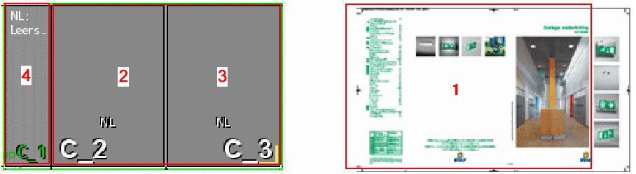
The flap is defined as a "Single Page for Folding Sheet". The page is automatically dimensioned to fit perfectly when it overlaps the other two page positions including bleed.
The page is made bigger by the values specified in these boxes. In other words, material/paper is added for a larger trim. This changes the position of the page on the press sheet. The trimmed size, however, doesn't change.

Note: The values specified in these boxes affect the gap width that you can define in the Folding Sheet Inspector or in the "Schemes" step. You can think of these values as a minimum gap width that are always kept even if you enter a smaller value for the gap in the inspectors or place the pages on the sheet automatically ("Automatic Gaps").
You can hide the function using "File > Preferences > User Interface".
Makes a simple and automated production of small formats possible, e.g. small-format, square books or calendars. Several different single segments (e.g. small-format, square books) are grouped together to one large production folding sheet using the "Layers" function so that the single segments lie side by side. Cutting is done only after the last fold.
Folding sheets with special master pages can also be segmented.
The automated function calculates the target size (trimmed size), the bleeds and outer edges of the single segments on the sheet from the sizes and data you entered, it shows the 1ups in different colors and sets the cut marks.
To set a mark for each segment, select a mark with the "Segment" placeholder in the "Marks" step > "Folding Sheet Label".
Folding sheets are segmented
"Automatic" segmenting of the folding sheets starts.
Size of Single Segment/Page after Separating Cut
Enter the target size you want (trimmed size) of the single segment (e.g. size of the small-format, square book).
The trimmed size changes automatically in "Master Page Types".
Segment Order on Folding Sheet
Copies X, Y: Enter the number of segments that are to be side by side (X) or one below the other (Y).
A layer is created automatically for each segment (copy) in "Job Inspector > Number of Layers". The layers can then be filled later several times with the quantity you want.
Copying is possible in one direction only. A value is automatically reset to "1" if your input is wrong.
The trimmed size changes automatically in "Master Page Types", the copies are added up corresponding to the trimmed size.
Distance? - ?: The list box lets you select segments side by side or one below the other. In the box beside this, you enter the gap required. This means that you can have different gaps.
Placement rule for assigned pages
This is where you set how the PDF page content will be placed within the trimmed size.
Automatic
"From Trim Box" is the factory default in the "Imposition/Automatic Imposition" modes.
In the "Packaging" and "Montage" modes, the factory default for "Placement rule for assigned 1ups" is "Center" (scaling 100%, orientation 0 °, no mirroring). You can change this default in the Preferences.
When you select "Automatic", the default set in "Preferences > Defaults..." displays in parentheses. The optional settings cannot be seen.
See Defaults for Master Pages (Placement Rule).
By user (view options)
When this option is set, custom options are added to the group.
Possible Placement Rules
•"From Trim Box": In this option, the trim box is fit to the trimmed size. The bottom left corners are the reference points (equivalent to "Automatic" in "Imposition/Automatic Imposition").
The trim box at Signa Station is defined as follows:
·Case 1: The PDF page has a trim box. The trim box at Signa Station is then fit to the PDF trim box.
·Case 2: The PDF page doesn't have a trim box but a crop box. The trim box at Signa Station is then fit to the PDF crop box.
·Case 3: The PDF page has neither a trim box nor a crop box. The trim box at Signa Station is then fit to the PDF media box.
•"Center": The page content is centered on the trimmed size if you select this option. This option is helpful if the user data are centered on the PDF pages (equivalent to "Automatic" in "Montage" and "Packaging").
•"Custom": This option lets you define your own offset for the data page in relation to the trimmed size in X/Y direction.
You can define settings for scaling, orientation and mirroring for all three offset types.
For more details about the bounding boxes, see the "Glossary".

Note: All settings that you define in "Placement rules for assigned pages" overwrite any settings made in the Page/1up Inspector.
The step is enabled only in the "Imposition" and "Automatic Imposition" work modes.
You can set the following parameters in the "Binding" step:
•Select the binding method
•Enable creeping and define values for it
•Enable automatic bottling
•Define a gripper margin for front or back fold
•Define cover bonding for residual glue (web)
•Define a glue line (web)
•Define defaults for automatic gap computation
(see also Overview of Gap Computation)
•Assign cut blocks
Signa Station automatically defines the pagination and any necessary creeping for the selected binding method (pagination depends on the folding scheme/folding rule you selected).
The trim for the pages at the back margin is set to the value defined in "Preferences > Trim ... in routing margin" if you use a binding method that includes a routing margin. Normally, the routing margin should not have any print data.
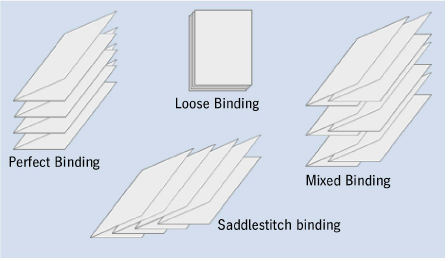
In perfect binding, the folded sheets are placed on top of each other, milled off at the back and glued.

Note: Automatic gap computation generates a gap between the left and right page that is equivalent to the maximum routing margin.
In saddlestitching, the folded sheets are nested. As a result, the final page number of the assembled page not only depends on the folding scheme selected, but also on the size of the publication.
In this binding method, the application automatically pairs up the highest and the lowest page numbers and then calculates the number that each individual page will really have.

Note: Automatic gap computation set the gap between the two-page spreads to 0 mm.

Note: In the "Product Part" step, you can also set the "Binding Type for Gluer" that is written to the output JDF and can be used in postpress for machine presetting. This setting has no impact in Signa Station.
In the "Come & Go" binding method, the first and last book block are printed on one folding sheet, the second and second last block together, then the third and third last, etc. The folded sheets are stacked one on top of the other until the middle is reached or passed. The last fold between the two blocks is not made. Instead, the sheets are cut. Now both piles of blocks are placed one on top of the other. In this way, your book is produced.
Additional 1ups of parts of a book can be produced by utilizing a folding sheet to print additional book blocks that are also cut off and then gathered with the other blocks. The aim is to produce smaller folding sheets (less creeping), to fold less folding sheets and to save a cut on the cutter by using the separation cut on the folding machine. This process is used often for small-format books (soft cover).
Page numbering is the same as in saddlestitching. Creeping values, on the other hand, are similar to those in perfect binding. However, the creeping values depend on the folds done and, for that reason, are not fully identical. This means that different values are calculated when the binding method is changed. For example, in an F-08 scheme in Come & Go, creeping of the two folding sheet halves would be equivalent to creeping of an F-04 scheme in perfect binding.

Note: Automatic gap computation generates a gap between the left and right page that is equivalent to the maximum routing margin.
This option also allows you to image two book blocks on one folding sheet. One block has ascending page numbers, the other descending page numbers. In other words, mirror-inverted sheets are produced, with two whole books being imaged. This mode is used if the plates had been necessary anyway because of the number of sheets or if rotation of the first folding sheets would result in an inaccurate production. Generally, closed and open sides of the folding sheets alternate.

Note: If you create a product part in this binding mode, the number of pages is automatically doubled and twice as many folding sheets created. For example, to print a book with 48 pages, enter 48 pages as your page total. You need three folding sheets for this. Signa Station, however, doubles this number to 96 pages and 6 folding sheets.
Automatic gap computation generates a gap between the left and right page that is equivalent to the maximum routing margin.
In this binding mode, a stack of sheets can be divided into two parts after printing, with one part consisting of the upper half of the page numbers and the other of the lower half. For example, in a 16-page book, one stack has pages 1 thru 8 and the other stack pages 9 thru 16. For this to be done, you must create a folding scheme where the page numbers make allowance for this, e.g. after folding for two pages, 1-3 (front), 4-2 (back).

Note: Automatic gap computation generates a gap between the left and right page that is equivalent to the maximum routing margin.
This binding method includes different binding modes, namely perfect binding and saddlestitching.
For example, three folding sheets are assembled to one book block with saddlestitching. Afterwards, the book blocks are compiled to one book with perfect binding or thread-stitching.

Note: Automatic gap computation set the gap between the two-page spreads to 0 mm.
In the Loose Binding mode, you can create all the gaps the same, at least on the right and left. This means that all the sheets are the same, that they are not folded but just cut, for example, punched sheets in a loose leaf binder.

Note: Automatic gap computation divides up the available space evenly between all gaps.
In a publication with thread-stitching, the folded book blocks are stacked on top of each other, with the sheets bound by thread.
This method is analog to perfect binding but there is no routing margin.
In a publication with a leaflet fold, the pages will not be cut. This means that the spacing between the pages must not change.

Note: Automatic gap computation set the gap between the two-page spreads to 0 mm.
This setting is for books in Arabian-speaking countries. In such countries, books are opened from left to right and read from left to right. You must create a special folding scheme for this.
The function is not suited for the "Come & Go", "Come & Go Two Books" and "Cut and Stack" binding methods. The setting switches automatically to "Perfect Binding" if you select one of these binding methods.
The pagination of a 36-page publication is affected as follows when you enable the option:
•"First and Last"
The cover has pages 1, 2, 35, 36.
•"First"
The cover has pages 1, 2, 3, 4.
•"Last"
The cover has pages 33, 34, 35, 36.
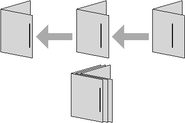
This function now makes it an easy matter for you to place cover pages, for example, to the beginning or end of a custom PDF document.
In addition, automatic mechanisms are handled as follows:
•The folding sheet concerned is ignored in the calculation for creeping.
•The folding sheet concerned will not have any collating mark. Collating mark "1" will be placed on the second folding sheet.
•The folding sheet concerned is ignored in the "sort for bookbinding" function.
Sort Folding Sheet for Bookbinding
Bookbinders generally want that smaller folding sheets (half sheets, quarter sheets or even light-weight sheets) are not at the end of a book block. This function automatically repositions the sheets accordingly.
You can also enable this option manually in Sort Folding Sheet for Bookbinding using the context menu in the "Schemes" step > "All Folding Sheets" if a folding sheet is selected.

Note: In the "Schemes" step > "Gaps and Master Pages" and "All Folding Sheets", red font draws your attention to the fact that the option was already enabled.
Twin lay jobs are those where two different products are processed in one scheme.
A folding scheme contains two products. Exactly this method is also used in the "Come & Go" binding method, i.e. "Come & Go" is a special variant of the twin lay method. But there is a restriction: the folding sheets of both products cannot be moved due to color or other requirements. It is not possible in this way to combine folding sheet 1 of product 1 and folding sheet 3 of product 3 on one press sheet because they contain the same spot color, for example.
The twin lay method in Signa Station meets these demands universally. This requires that you can split a folding scheme into a maximum of two sections and that this division is always horizontal. You enable the "Twin Lay" mode in the "Binding" step of the Assistant/Product Part Inspector. You can select this option only with allowed binding methods (at present, perfect binding, saddlestitching and thread-stitching). The "Change Section Order" button in the "Schemes" step becomes operable when the Twin Lay option is enabled (see Section Handling ).
For saddlestitch-bound publications (such as magazines), the paper thickness makes the inner pages shift outward (i.e., away from the spine). If the publication is trimmed after binding, the inside pages will have narrower outer margins than the outside pages. The same is true for perfect binding when large sheets with many pages must be folded often.
This schematic diagram shows how the required value for creeping is determined in saddlestitching.
Creeping Off
The function is disabled and ignored.
The creeping values are calculated automatically from the paper thickness if you select this option. You can generate or modify the paper definitions in the "Plates" step or in "Papers (Printing Materials)" in the "Jobs & Resources" menu > "Resources & Machines". See also Papers (Printing Materials).
The function makes automatic creeping in X and Y direction possible.
•Creeping by
You can choose between "Offset" (default) and "Scale". With scaling, the pages become bigger or smaller depending on their position in the scheme to stay the same at the back margin and match them to the nominal position on the outer edges.
•Paper Thickness Factor
The paper thickness is multiplied by this factor to get the creeping you want for each sheet.
Enable this option if you wish to enter your own inner/outer creeping values. The values refer to all the folding sheets in the product part. The data for "Inner" and "Outer" always refer to the first scheme of the product part. The program calculates creeping per sheet from these values and applies it to the entire product part.
•Dual Direction Creeping (see "Automatic")
•Creeping by (see "Automatic")
•Creeping Value Inner
This is where you enter the value by which the innermost pages of the first scheme have to be offset to compensate for their creeping.
•(Creeping value) Outer
This is where you enter the value by which the outermost pages of the first scheme have to be offset to compensate for their creeping. The difference between the internal and external adjusted margins is the creeping margin. By entering positive values, you will shift the pages outward; by entering negative values, you will shift the pages toward the spine.
The distances between all the other pairs of pages in the book will be calculated according to these extreme values. The creeping margin values are related directly to the page spacing you have set in the scheme, see also Folding Scheme Editor . These values will be added to or subtracted from the page spacing.
For more details about enabling creeping for a single page, see Creeping.
The scheme used determines whether automatic creeping is possible or whether manual creeping is necessary.
Generally, the program can calculate the required creeping margin values itself.
AutoBottling
Remember the following conditions when you enable this function:
•Binding Methods
Automatic bottling is not allowed with "Come & Go" and "Cut & Stack" binding methods.
•Folding Sheet
The folding rule must end with a cross fold, e.g. "x1Y1", and may not have a minus sign.
•You may not make any changes or corrections to the scheme after you enabled the automatic function.
•In web presses with ribbons, combinations with single pages and 3/4 pages may result in problems.
•"AutoBottling" must be disabled if you use the scheme "F16-11_li_4x2".
•Fold types "zigzag" and "letterfold" can be problematic.
•Pagination
The "Accordion Fold" pagination mode may not be selected in the Folding Scheme Editor.
More information about "bottling" and what manual corrections you can make can be found in Bottling .
Gripper Collator / Cover Bonding / Glue Line
Normally, a strip of paper/material is used to pull the folding sheets on to the saddle if a saddlestitcher is used to collate the sheets. The position of this strip on the sheet depends on the folding sheet scheme and basically means that the folding scheme is slightly asymmetric on the paper sheet.
Signa Station's automatic gap computation includes the values you enter for this option and calculates all the gaps so you have the correct front and rear gripper fold after folding.
•(No) rear fold/front fold
There is no gripper margin for the saddlestitcher or there is a page offset for a gripper margin for the rear or front fold. You must enter the values in "Size of Gripper Margin".
This is where you define the size of a page offset for the rear or front fold for the gripper margin of the saddlestitcher.

Note: When this function is set, the values display in the "Schemes" step. In addition, the function can be seen.
Only displays if "Show check items for cover bonding and glue line" is enabled in "File > Preferences > User Interface > General".
In "Cover Bonding", space is added to the folding sheet paper. In book production, this additional space must be created at the lower edge of the cover so that residual glue can be absorbed when gluing the cover to the book and that it does not flow into the pages.
•None
•On the First Folding Sheet
Paper is added to the first folding sheet of the product part.
•On the Last Folding Sheet
Paper is added to the last folding sheet of the product part.
Only displays if "Show check items for cover bonding and glue line" is enabled in "File > Preferences > User Interface > General".
A glue line is needed when producing booklets with web presses. A glue line is automatically applied before folding. This serves the purpose that no further gluing is needed after folding.
The folded double pages are glued together at the sides along a narrow strip in the back margin. This line is not noticed when leafing through the pages.
There should be no color in the glue line as this could impair adhesion.
This can be done in one of the following ways:
•By Moving
You can move the content of each page affected away from the back margin by the value set in "Glue Line Width".
•By Scaling
The visible page content is retained and scaled (made narrower) so that the glue line in the back margin of each page is kept free by the value set for width.
•By Clipping Only
The page bleed becomes smaller.
•Outermost Pages Only / Include Inner Pages
Normally, the glue line is defined on the outermost pages. However, in certain production conditions, it may be wanted also on the innermost pages (for example, to glue a cover to a booklet). Choose the option accordingly.
•Glue Line Width
Enter the width you want for the glue line.
Parameters for Automatic Gap Computation

Note: See also Overview of Gap Computation
Automatic Gap Computation
This setting lets you select where the setting for automatic gap computation comes from. If "Use for JDF Import" is enabled in a product part template, then during a JDF import with a product part template the setting for automatic gap computation from the Preferences is not used but the setting from the product part template.
In this way, for a specific job you can switch between the Preferences and the product part template as the source.
If automatic gap computation is enabled, it is no longer possible to specify the gaps manually in the "Schemes" step. The gaps are calculated automatically when a new scheme is added. If automatic gap computation is not to be done for a scheme, you can disable it for the selected scheme with "No Automatic Gap Computation" in the "Schemes" step.

Note: In Automatic Gap Computation, the head and foot trim are calculated separately and asymmetric trims are generated if this would make the folding sheet margins extend to the paper margin.
Routing margin
•This displays the default value for a routing margin. After you enable the "Use routing margin" option, the value is applied in the product part and you can also change it manually in this box.
The value is taken from the preferences in "File > Preferences > Defaults > Routing Margin Min.".
Use this option to define whether or not a routing margin will be included. You can disable the function as you may want to impose a job with thread-stitching as a job with perfect binding (there must be no routing margin in thread-stitching).

Note: Automatic matching of the routing margin is ignored if special master pages are defined in a job as this would otherwise give you incorrect results.
Max. Head Trim/Max. Foot Trim/Max. Gap
The value entered is used for the automatic calculation of the gaps (in the "Schemes" step) when you check this option. If "Max. gap" is specified and the options for foot and head trim are not enabled, the value for the gap is also used for head and foot trim.
The value for Max. Head Trim only affects the page head, the value for the max. gap all the gaps. The gaps are created only up to the size entered, even any larger head trim, if Max. Gap is enabled. This means that the folding sheet can be smaller than the paper.
Analog to the maximum head trim, during automatic gap computation the gap at the foot of the page is set up to the entered value as a maximum. This can be necessary if you are working with a saddlestitcher/perfect binder that aligns the signatures on the foot or, in the case of multiple 1ups, with high quantities in finishing.
Remember that the extra space in the "Master Pages" step is taken to be the minimum gap and the maximum gap is added to this. The automatic gap is used if you disable the maximum gap. In this case as well, remember the values you entered in the Preferences > "Defaults" tab.
Gaps between a two-page spread such as routing margins are not affected by this.
For example, if the gap at the head is always to be exactly 10 mm, then enter 5 mm in "Master Pages > Trim Allowance for Pages > Top", set Max. Head Trim to 0 mm and check the box. The head trim is now automatically exactly 10 mm when the gaps are calculated automatically.
"Minimum head trim/Minimum foot trim/ Minimum gap"
As with the maximum gap, minimum values for the gap can also be specified. If the specifications for the minimum and maximum values contradict each other, for example because a minimum value is greater than a maximum value, the corresponding values are displayed in red and the maximum values are used for the calculation.

Note: The calculation of gaps may differ from the settings in the "Plates" step for automatic subject positioning. In this case, the specifications in the "Plates" step apply and warning icons appear in the fields for the gap calculation in the "Binding" step.
In the "Imposition" and "Automatic Imposition" modes, it is also possible to customize the cut block to meet your different needs.
Cut blocks that are defined as described below are written to the data for a CIP3 or JDF output and as a result their data can be used by cutters.
Cut blocks are shown as a "green line" in the graphic window.
To pages/1ups
The single pages on a folding sheet automatically become cut blocks.
This can be a good idea if a scheme with the same page numbers, e.g. when you create postcards, was selected. Generally, however, the "Montage" mode covers this type of production.
To folding sheets
Folding sheets including their margins automatically become cut blocks.
This is what you normally want and is the default.
To scheme
Only the scheme without the folding sheet margins becomes a cut block.
The margins must not be in the cut block if the folding sheet is to be trimmed to size before folding.
You will find a detailed description of how to work with marks in Working with Marks.
You can set the following parameters in the "Marks" step:
•Set/remove automatic print control marks
•Define positioning, colors and scaling for automatic marks
•Confine the placement related to the folding sheets

Note: When a job is reloaded, the marks and automarks sets used are compared with the current resources and can be refreshed if needed. Automarks sets modified in the job (tagged by "*") are not automatically synchronized.
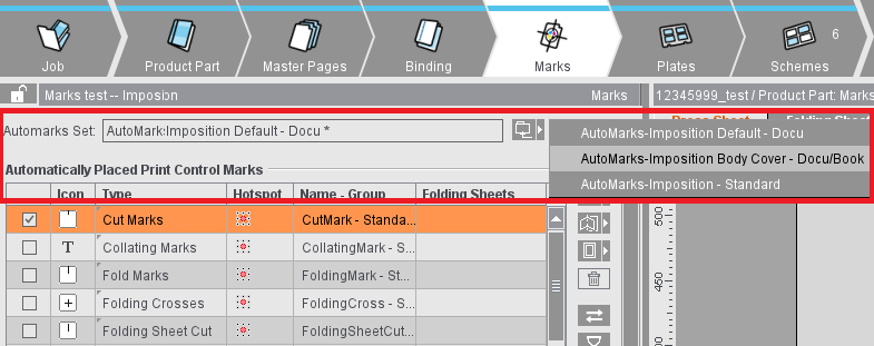
Automatically Placed Print Control Marks
Cut marks, fold marks, collating marks, folding crosses, folding sheet cuts, fold lay marks, 1up ID, 1up cover clip path mark and folding sheet labels are automatically set for the product part if you enable this.
In a new job, the automarks set defined in the Preferences for the selected work mode is used. The set used displays in the "Automarks Set" box. In the job, you can select a different automarks set from the Resources using the folder button or customize specific settings for the job. The automarks set used and the Resources folder display in the upper box. Only the automarks sets matching the selected work mode display in the "Choose Mark" dialog.
In the Preferences as well as in the Product Part Template Editor (with the "Use automark set group" option enabled), you can specify an automark set group instead of a specific automarks set; this means that all automark sets from a specific resource folder will be included in the newly created job
Changes to the automarks set affect only the job in question and not the resource. Automarks sets that differ from the resource are tagged by a "*". During a comparison of the settings within the job with the resources, modified configurations are ignored to avoid unwanted changes within the job. You can also save the modified set from the job to the Resources using the Save button (either as a new set or by overwriting an existing set).
You can create and edit automarks sets not only in the Resources but also in the job in the "Marks" step and save them to the Resources from there. The editor for creating automarks sets in the Resources and the editor in the job have only slight different functions. To give you a better overview of the use of automarks, the topic is described in a separate section: Automarks
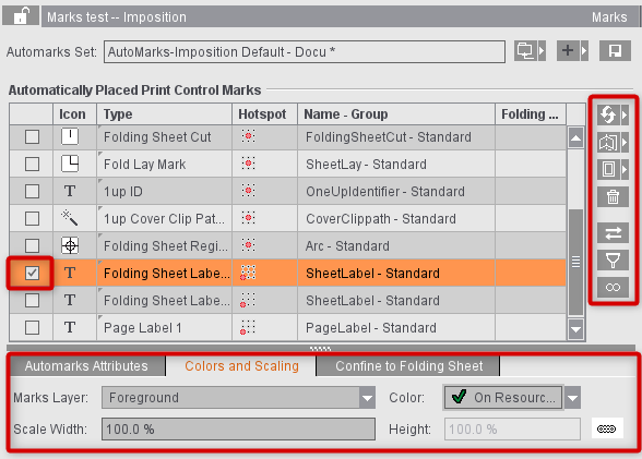
The table gives you a clearer overview of the default parameters and configuration of the print control marks:
•When you select an inactive mark, its parameters show below the table (cannot be edited).
•When you enable and select a mark, you can edit its parameters below the table:
The automatically placed cut and fold marks cannot be changed for now because the positions of these marks are always unique. You can modify them only by explicitly disabling the automatic function in the graphic window. More details can be found in Automatic Function for Automatic Cut and Fold Marks.
You can then select and modify all other automatic mark types in the graphic window.
You can find details about the settings for marks in the following sections:
|
Auto marks sets for imposition (setting options in the editor) |
||
|---|---|---|
|
|
||

Note: The "1up ID" mark was designed especially for gang jobs or for multiple sheet optimization. More details can be found in Introduction to a Gang Job with Sheet Optimi-zation.
When cut and fold marks are set, the program always checks whether the gaps on the folding sheet/assembly block are big enough for the automatic marks and for the page bleed. If necessary, the marks are deleted and the bleed reduced so that they don't jut into the adjacent page. This applies for front and back printing.
The cut and folding marks can no longer be modified. These elements are indicated by a red frame in the graphic window when you select them.
The automatic fit for bleeds is not used if a custom bleed is set on a special master page. There are special cases where a bleed must jut into the adjacent page. You can allow this by creating a special master page with a custom bleed ("Master Pages" step). In addition, you can disable the "AutoReduce Bleed" option in the Page/1up Inspector.
The cut marks are set in relation to the page and are listed in the Page/1up Inspector in the "Marks" step (see also Page/1up Inspector).
The fold marks, folding crosses, folding sheet cuts, fold lay marks and collating marks are set in relation to the folding sheet and are listed in the Folding Sheet Inspector in the "Marks" step (see also Folding Sheet Inspector, Marks).
Automatically placed print control marks are set per folding sheet or page. Using rules, you can use different automarks configurations within a job, depending on the folding sheet. For example, the cover is to have different marks and parameters to the body or there are to be different marks configurations for various customers.

Note: At present, you can create rules only for automarks configurations for the "Imposition" work mode.
For more details, see: Automarks
Manually set marks are handled based on the following rule:
All folding sheets and press sheets are fully recalculated if you change the layout in the product part, e.g. page size, gaps, paper size. etc. In this case, any manually set marks are lost. The layout is not recalculated and the marks are kept with other types of changes such as creeping on/off, position of the page contents, etc.
You can only select automatically set marks in the "Marks" step. You can set manual marks in the Press Sheet Inspector, Folding Sheet/Assembly Block Inspector and Page/1up Inspector.
Assembly block labels (Montage only)
You can use this automatic mark only in the "Montage" work mode. The mark is not set by default.
Marks that provide additional information about the assembly block are required analog to the folding sheet label in the "Imposition" mode.
Precutting marks (Montage only)
You can use this automatic mark only in the "Montage" work mode. The mark is not set by default.
Precutting marks are set on the margins of the assembly block. If precutting marks are active and set for the selected assembly block, a check is also run to see whether the gaps are at least the sum of the margins. This check makes sure that, when two assembly blocks abut each other, the precutting marks of one assembly block do not cut away the content of the other assembly block. If this is done, a warning triangle displays in the "Gaps" text box. Your attention is drawn to the issue in the tooltip of the text box.
Precutting marks may jut into another page when these marks are used for CAD assembly blocks (e.g. if the CAD assembly block does not have a shape). Nevertheless, precutting marks are wanted for precutting assembly blocks.
You can control whether the precutting marks will be removed or kept with the "Delete, if this juts into another page" option.
Precutting marks are placed in relation to the 1up. This places them on all corners of each 1up. Enable "Set Outer Marks Only" if the pre-cutting marks are to be placed only on the outer corners and inner 1ups are not to have any pre-cutting marks.
You can use the automatic mark in the "Imposition", "Montage" and "Packaging" work modes. The 1up cover clip path mark creates a clip path having the size of the 1up including the bleed. The mark is not set by default.
A "1up Cover Clip Path Mark" is set automatically to every page/1up with this type of mark. This prevents marks set to "Background" jutting into the page/1up content or overlapping white parts within the bleed box.
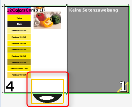

Note: If the 1up cover clip path mark causes flashes, for example because an ink pickup mark is placed in the background, you can specify a size change (larger/smaller) of the 1up cover clip path mark in the "Automarks Attributes" tab.
List of Selected Plate Templates
The plate templates selected for the product part are shown in the list.
Using the buttons on the right, you can load or replace plate templates to the product part or remove them from there:

Note: The paper size does not change. An error message displays if the paper already defined has become too big because of the different plate. In such a case, first change the paper size and then replace the plate.

|
Recycle bin You can delete the plate template selected in the list and its values from the product part by clicking the trashcan icon. |

Note: For plate templates with automarks sets and not manually placed marks, the "Automarks" tab that displays the integrated press sheet automarks set and the automatically placed print control marks and their settings (see Automarks sets for press sheets for details) will be displayed in addition to the "Attributes" tab.
Selected Plate Template
This displays the selected plate template in the required size.
You can also create or modify plate templates in "Plate Templates" in the "Jobs & Resources" menu, see also Plate Templates .
Can only be used in the "Imposition" mode.
You can place different folding sheets on the plate template if you select this option.
A gang run form is different from normal plate templates in that only the exact number of press sheets you set in "Number" is created. The folding schemes are placed only on the first press sheet, the others are generated automatically based on the same pattern.
The "AutoPosition Subject" function is disabled if "Gang run form" is enabled.
The position and orientation of the folding schemes is set in the "Schemes" step > Active Inspector Section, "Press Sheet Layout". See Press Sheet Layout.
Number
Can only be edited if "Gang run form" is enabled.
This is where you define the number of press sheets that will be created with the plate template.
Press Sheet Variants
Only available if you are working on a job with versions (Job Inspector "Number of Layers" >1, "Versions" minimum of 1).
You can create several variants of one press sheet. The difference between the variants is the assignment of different versions to the folded sheets (or page positions). Apart from that, the variants do not differ. This method is similar to a 1up optimization. You go by the quantity of the single versions when you combine the versions on the press sheet variants. In doing so, you try to optimize the quantities of the single press sheet variants and minimize the surplus of each version.
Content on Banner (for Digital Web Press Only)
The banners are included during output when this option is enabled.
Banner Count (for Digital Web Press Only)
Specify the number of various banners that will be repeated on the positions (can also be set in the Press Sheet Inspector).
Work Style
This is where you can change the rule for generating the back sheet (perfecting).
This is what you have when the front consists of single plates and no plates will be created for the back.
This is what you have when the front and back are on one plate. As a result, you do not need a plate for the back. The stack of paper is turned after printing and the back is printed. The operator doesn't need to load a new plate.
Explanation of "Work-and-turn": The stack is turned from right to left after printing. The side that is not yet printed is printed now.
See "Work-and-turn", the stack of paper, however, is tumbled after printing.
Explanation of "Work-and-tumble": The stack is turned from front to back after printing. The side that is not yet printed is printed now.
Two plates are created for printing, one for the front and one for the back. The stack is turned from front to back after printing the front. A perfector in the press does this.
Two plates are created for printing, one for the front and one for the back. The stack is turned from right to left after printing the front.

Note: For the "work-and-turn" work style (also single-sided), the subject is always placed on the plate beyond/above the gripper margin. The minimum space between subject and gripper margin is equivalent to the page trim of the left master page. For the "Perfector" work style (also single-sided), the subject is centered horizontally and vertically on the plate. If you want centering for "work-and-turn" as well, you must check "Center subject" in "Preferences > Defaults".

Note: Only active if "Work-and-turn" or "Work-and-tumble" is selected in "Imposition/Automatic Imposition" and "Ganging Optimization"
If several folding sheets are positioned on a press sheet, you can push them apart by defining a separating gap in this box.
Paper Definition for Production
This shows the paper that may have been selected when creating the job and that you can change for the current job.
In "File > Preferences > General", it is possible to make the "Name" section editable. See Paper Name Editable.
The paper thickness affects creeping, see also Creeping and Bottling.
You can assign the job a paper type or create one for it by displaying the "Choose Paper (Printing Material)" dialog by clicking the folder button to the right. You can also do the same for the paper size.

Tip: By entering a partial string of the resource you are looking for in the search field at the top, you can restrict the display to all resources that contain this string for a better overview.
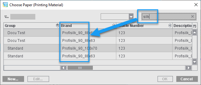
You can also create or modify papers and paper sizes in the "Jobs & Resources" menu > "Resources & Machines" in "Papers" or "Page and Paper Sizes". See also Page and Paper Sizes.

Note: If a paper is selected whose height is set to "0", the "Height" box changes to "Segment" and by default has the value for "Paper Segment" specified in the plate template.
The current paper size in the job is overwritten by default by the paper size stored in the MDS when a paper is selected from the MDS.
Because you do not always want this default behavior, you can now keep the paper dimension in the job when you set this option.

Prerequisite: "Show check items for cover bonding and glue line" must be enabled in "File > Preferences > User Interface".
Only makes sense to use this in web printing.
You can define the width of each roll (list box beside it) if you have multiple webs.

Prerequisite: "Show check items for cover bonding and glue line" must be enabled in "File > Preferences > User Interface".
See Center offset.
AutoPosition Subject
The lower edge of the subject is positioned on the lead edge (blue line) with a distance of the bleed at least.
You can change the subject position manually if the option is disabled.
Center Subject Vertically/Horizontally
The subject is centered in vertical (Y) or horizontal (X) direction. If the options are not selected, you can define a set offset of the subject to the lower edge and/or the left edge.

Note: Please note: Input of the value of "0" for the "Left" offset does not mean horizontal centering like in the program versions up to 2018 but actually positioning exactly on the left side. As of version 2019, jobs from program versions up to 2018 where horizontal centering was set with "Left offset = 0" open automatically with "Center Subject Horizontally" enabled.
Consider Gripper Margins and Non-Printable Margins
During the automatic calculation of the number of 1ups, this includes the gripper margin and the areas for lead edge of print and tail edge of print as well as the margins on the side as set in the machine parameters. The option does not affect the whole product part but only the plate concerned. As a result, you can define, for example, different settings for cover and body. You can generally enable/disable the option in the Preferences in "Defaults > Subject Settings".
When the option is enabled, a warning will be issued if subject, folding sheet, bleeds or marks are found in one of the critical areas during output. This includes the following areas:
•off the paper
•on the gripper margin
•in the non-printable area/tail edge of print
Points to note for "Plates" in the "Ganging Optimization" mode
Automatic Paper Height Reduction
Signa Station automatically calculates the maximum paper height required of each resulting press sheet.
•"Ganging Optimization without Layout Default": according to the settings, the paper height is reduced automatically to the subject plus set margins.
•"Packaging" and "Ganging Optimization Packaging": the paper height is reduced to make the subject with all the marks fit on the paper and to avoid collisions with press sheet marks.
•Use of sheet paper: In this case, the paper height is trimmed before printing. Possible field of application: Produce more unprinted waste and not printed waste.
Positioning the subject is possible in four ways. This process refers to the settings for the margins in the "Optimization" step ("Geometry Data for Sheet Optimization") and, where applicable, the placement defaults from "Advanced Settings... > Placement".
The subject settings affect the final optimized result only after the 1ups were placed. This means: Changes to the subject settings do not affect the optimization result but only the placement of the result on the paper.

|
The subject is centered on the paper horizontally and vertically, regardless of the placement defaults in "Advanced Settings...>- Sheet Optimization Setup > Placement". |

|
The subject is centered horizontally on the paper. The vertical position is - according to the placement defaults - within the area defined by "Margin Top" and "Margin Bottom". |

|
The subject is centered vertically on the paper. The Horizontal position is - according to the placement defaults - within the area defined by "Margin Right" and "Margin Left". |

|
The subject is placed according to the placement defaults defined in "Advanced Settings...>- Sheet Optimization Setup > Placement" within the area specified by the margins. |

Note: If the result of centering on the paper in one direction or both directions is that the subject extends beyond the margin set under "Geometry Data...", the subject will be moved to this margin accordingly, i.e. the values for the margins will always be taken into account.
You can specify which subject setting is used to insert a plate template by default in Preferences under "Defaults > Subject settings" (see Subject Settings).
If you change the subject settings in the "Plates" step, you must click the "Optimize" button again in the "Optimization" step for the change to take effect.
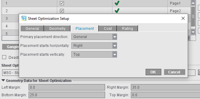
Examples:
Placement "Right" and "Top", "Right Margin" 35.0, "Margin Bottom" 25.0 (see screenshot above)
The blue dashed line identifies the area set by the margins.

|
|
Centered on the paper in both directions, within the margins. |

|
|
Placement "Top", Top margin= 0, horizontally centered on the paper |

|
|
Placement "Right" at the set margin, vertically centered on the paper. |

|
|
Centering switched off: Placement "Top" and "Right" at the set margin, to margin = 0, right margin = 35.0 |

|
|
Placement "Top", Top margin= 0, horizontally centered on the paper |
Points to note for "Plates" in the "Packaging" or "Sheet Optimization" mode
For packaging jobs, it is also possible to load several plate templates in order to load and optimize different cutting dies on the related press sheets.
For that reason, you can load more than one plate template for "Packaging" and "Ganging Optimization Packaging" jobs in the "Plates" step.
In the lower part, "Subject Settings" is added to the setting options for the plates. This is where you can set the positioning for the plate template selected in the table. This setting is used as the default when creating press sheets.
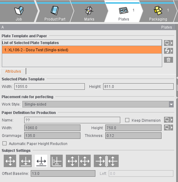
Automatic Paper Height Reduction
Signa Station automatically calculates the maximum paper height required of each resulting press sheet.
•"Ganging Optimization without Layout Default": according to the settings, the paper height is reduced automatically to the subject plus set margins.
•"Packaging" and "Ganging Optimization Packaging": the paper height is reduced to make the subject with all the marks fit on the paper and to avoid collisions with press sheet marks.
•Use of sheet paper: In this case, the paper height is trimmed before printing. Possible field of application: Produce more unprinted waste and not printed waste.
Subject Settings (positioning of the cutting dies)
The settings for the positioning of cutting dies are kept permanently. This allows the positions of the cutting dies to be restored automatically after changes to the job (e.g. change in paper size).

|
Manual positioning There is no automatic mechanism for the positioning of the cutting dies. This condition is also valid whenever the position of a cutting die is edited manually, either by entering a value in the text box or by moving the cutting die in the graphic view. The data of the user interface elements below the table refer to the cutting die selected in the table above. Only if all the selected cutting dies have the same values do these also display. If the values differ, elements remain empty. |

|
Centered horizontally and vertically on the paper All the cutting dies are distributed evenly in each direction and centered as a whole to the paper or half of paper. If this is not possible because there is not enough space, then the cutting dies are arranged one below the other and centered to the paper or half of paper. |

|
Centered horizontally on the paper and vertically on the gripper margin |

|
Centered horizontally and positioned vertically with a variable offset to the lower paper edge |

|
Positioned horizontally with a variable offset to the left paper edge and vertically with a variable offset to the lower paper edge |
|
|
In the following two variants, the paper is cut through the vertical center: |

|
The cutting dies are centered horizontally and vertically on both halves of the paper |

|
The cutting dies are centered horizontally on both sides of a "virtual" gripper margin and vertically on both halves of paper |
|
|
The "virtual" gripper margin is an imaginary area if the paper would be cut through the vertical center and a gripper margin would be applied to the resulting cut edges. The cutting dies are positioned on both sides of the "virtual" gripper margin. |
Automatic positioning of the subject is enabled by default. Automatic positioning is disabled when you manually place a cutting die by entering positioning values or moving it in the graphical view. In the "Plates" step, a warning icon is also displayed in the "Subject Settings" line if the automatic positioning of the subject is disabled on at least one of the press sheets of the selected plate template.
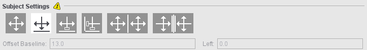

Note: See also examples for positioning in Positioning of Cutting Dies Depending on Work Style and Margin
The step is enabled only in the "Imposition" and "Automatic Imposition" work modes.
This is where you check, modify and create all the folding sheets for the current product part. Besides selecting the folding scheme, you can modify gaps, assign special master pages, use the bottling function, organize your press sheet, edit gang run forms and create folding sheet groups.
Page Assignment & Master Schemes (only for the 'Imposition' mode)
Placeable Pages
This refers to the number of pages specified for the product part that are to be placed on the selected folding sheets. You cannot change the number of pages in this box. You define the page total in the "Product Part " step, "Imposition" mode.
Unplaced pages
This shows the number of pages that still are not placed on the folding sheets created so far. In certain cases, negative values are shown in this box, for example, if the page total was reduced at a later point and there are now more folding sheets than required.
If you increased the number of pages, you can match the number of folding sheets accordingly in "Number" in the table.
The product part is ready when the number of unplaced pages is zero.
This list shows the schemes selected for the product part with the number of placed folding sheets and assigned plates.
Using the buttons on the right, you can load or replace schemes to the product part or remove them from there or single out folding sheets:
Folder button
Click the folder button and select a created scheme in the "Choose scheme" dialog that then appears. It is linked to the plate template selected in "Printing Plate", and the press sheet with folding sheet displays in the graphic window.
Replace Scheme (button)
Click this button and then replace the scheme selected in the list by another one.

Note: The list only shows schemes with the same number of rows and columns as the one you want to replace. You can disable this filter function in the selection dialog.
To single out a folding sheet (button)
You can also trigger this function using the context menu in the scheme list in "Press Sheet". See Printing Plate for a description.
Trashcan (button)
You can delete the scheme selected in the list and all of its folding sheets from the product part by clicking the trashcan icon.
This is where you can check and change the currently displayed folding schemes and their folding sheets.
Scheme Name
Displays the scheme name. You cannot edit the name.
This shows the number of folding sheets that the selected scheme created. You can change this number, for example, to match page numbers that were changed. Double-click the box below "Number" and type in the new value.
Display of the plate template that is linked or will be linked to the selected folding scheme.
Select "Singularize Folding Sheets" (either with the button on the right or in the context menu) if a folding scheme is to be placed on a different press sheet (gang run form). A press sheet is then not linked to the folding scheme so that you can place the folding scheme later on the "correct" press sheet.
•Custom Gripper Front Fold/Rear Fold Settings
If the option is enabled, you can define specific settings for position and size of the gripper margin for each folding sheet.
•"No Automatic Gap Computation": If automatic gap computation is enabled, it is no longer possible to specify the gaps manually in the "Schemes" step. When this option is enabled, you can exclude the selected scheme again from the automatic gap computation defined in the "Binding" step.
•Click "Calculate Gaps" to calculate the gaps from the paper and folding sheet size so that the folding sheets and the paper have the same size.
The spacing shown for head, foot and gaps changes automatically.
This takes into account the set binding method:
·Saddlestitching and Mixed Binding: Gaps between two-page spreads are set to 0.
·Loose Binding: Gaps are distributed evenly.
·Other: Gaps between two-page spreads are set to the maximum routing margin, unless the routing margin is to be ignored during calculation. In this case, the inner gaps are set to 0.
•You can manually edit the spacing shown for head, foot and gaps.

Note: For information about gap computation in Signa Station, see also Overview of Gap Computation
You will see the "Special master pages.." button if you created a special master page in the "Master Pages" step. Click this button to open the "Assign master pages from list" dialog. Now select a row in the "Assigned master page" column. A list box displays where you can select the master page and assign it to the page. The page then has a green page number.
You can also assign different special master pages to the front and back in this dialog. This is required, for example, if the contents have different positions. Changes to a master page on the front means that changes are automatically made on the back. You can still modify this change if you wish.
or:
Click a page in the scheme display and assign a master page to this page using the context menu. The page then also has a green page number.
This requires that "several" is set in "Types" in the "Master Pages" step.
The selected folding scheme displays as a table and as an animated graphic in this section.
For mixed binding, it is necessary to split the folding sheets into groups that are then put together. This grouping can be done manually (see below). This means, however, that products can be produced fully automatically only with set page counts; if the page count changes, grouping must be done again.
You can automate this grouping based on certain defaults with "AutoGrouping". Subsequent changes to the page count are also taken into account in this process.

Note: Grouping is basically possible only in the "Mixed Binding", "Perfect Binding" and "Sewn" binding methods. Automatic grouping is not possible if ''Sort Folding Sheets for Bookbinding'' is enabled in the "Binding" step. The nesting of folding sheets within one folding sheet group occurs only with "Mixed Binding".
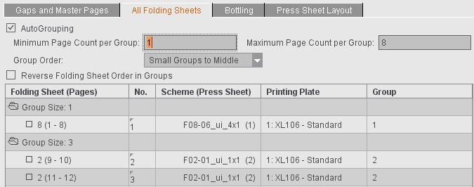
If AutoGrouping is enabled, you can set the following defaults:
•Maximum and minimum size of the groups. The data refer to the sum of pages of all folding sheets in a group.
The groups are formed in such a way that as few groups as possible are created on the whole and if possible no groups with a very small page count are formed.
If "First Folding Sheet is Cover" is active in the "Binding" step, a separate group for a folding sheet of the first scheme defined is created. "First Folding Sheet is Cover" is also possible with "Mixed Binding".
•"Small Groups": This is where you set the order in which the single groups will be sorted:
·"Front": The groups are sorted in ascending order based on their page count (= Small Groups First).
·"In Middle": The small groups are sorted to the middle of the folding sheet groups (= Small Groups to Middle).
·"Rear": The groups are sorted in descending order based on their page count (= Small Groups Last).
·"Second"/"Second Last": The small groups are sorted in after the first large group or before the last large group.
In order for a book to be bound firmly, it is necessary that the folding sheet groups with a smaller page count are not sorted to the beginning or end of a book block. If "In Middle" is selected, these groups may not be easy to find during the quality control. The "Second" and "Second Last" settings make sure that the smaller folding sheet groups are not at the beginning or end but can be found easily at defined positions.
•"Reverse Folding Sheet Order within Groups"
This changes the order in which folding sheets are placed onto the press sheet. Although the folding sheets of the first group are placed onto the first press sheet, the last folding sheet in this group is however placed first. This function is required for certain binders. It is not possible to reverse the order if "Constant Press Sheet Order" is active in the "Product Part" step.

Note: You can also use "Reverse Folding Sheet Order within Groups" independently of automatic grouping.
•Folding Sheet (Pages)
The number of folding sheets in the product part is shown after "Group Size". All the folding sheets incl. the pages placed on them are shown in a table if you open the "Group Size" folder by clicking the folder icon or with a double click.
Select at least one row to be able to create a new group or move the folding sheets using the respective function in the context menu:
·Create Group
You can create a new group only if you selected "Mixed Binding", "Perfect Binding" or "Sewn" in the "Binding" step. Please note that for "Perfect Binding" and "Sewn" the folding sheets within the folding sheet group are not nested but placed one after the other. Nesting occurs only with "Mixed Binding".
Mixed binding includes perfect binding and saddlestitching. The sheets in a group are saddlestitched and gathered and glued before they are bound together with the other groups, for example, by thread-stitching. The creeping values are calculated separately for each group.
A new group will have as many sheets as you selected, ignoring any group name.
You can use this option to move sheets to the position you want in the book block. (Index is the number in No.)
·Sort Folding Sheet for Bookbinding
Bookbinders generally want that smaller folding sheets (half sheets, quarter sheets or even light-weight sheets) are not at the end of a book block. This function automatically repositions the sheets accordingly.
You will also find this function in Sort Folding Sheet for Bookbinding.
•No.
Shows the new position of the folding sheet, defined by the index (context menu: "Move Folding Sheet").
Example:
You have four folding sheets. Folding sheet number 4 is given a new index, 1. Folding sheets 4 and 1 swap accordingly.
•Scheme (Press Sheet)
The folding scheme name of the press sheet is shown in this box.
•Group
Displays which group the sheet is part of.
You can use this function to study binding in a three-dimensional animated graphic.

Note: You can disable the option using the "parameter sets" in the Preferences to relieve memory. You can also use the parameter sets to define whether the display will be collapsed or expanded by default.
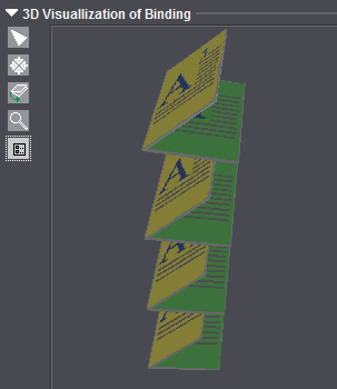
Button functions:

|
Deselects the other tools. |

|
Resets a rotated folding sheet to the way it originally was. |

|
Rotates and moves the animation. Click the animated graphic while holding down the mouse button and move the mouse pointer. To move the animation, hold down the alternative mouse button (PC: right mouse button, Macintosh: command key + mouse button). |

|
Zoom up graphic is set by default. A "+" appears in the magnifying glass. Hold down the "Alt" key to zoom down. A "-" appears in the magnifying glass. |

|
Opens a dialog where you can edit the animation properties such as colors of each of the components, or showing and hiding previews and folding sheet numbers. |
This function is especially interesting for very large sheets that will be folded several times with a cross fold. The "Bottling" function counterbalances a page rotation caused by a cross fold.
This slight rotation prevents wrong orientation of the pages that can occur during folding because of the large amount of material in the back margin.
When several pages of a large signature are folded into each other, the vertical alignment of the pages in the bound publication is no longer exact. The pages look slightly rotated outward or inward. With the "Bottling" function, you can specify a slight rotation in the opposite direction so that the pages are exactly aligned vertically when folded later.
The schematic diagram below illustrates how the angles are determined for "Bottling". The red dots are pivot points that are clicked and from which rotation is calculated.
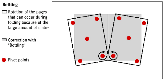
You will find a description of how to proceed in "Bottling" in the "Schemes" step. Select the "Bottling" tab.
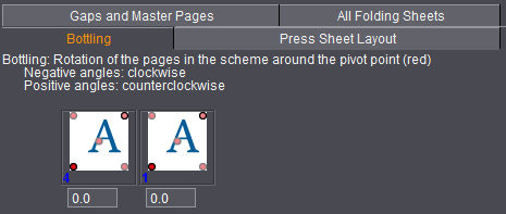
You can see the currently selected plate template with the set turning type (Sheetwise or Perfector) in the list below "Printing Plate" above the bottling editor. See also Printing Plate .
Bottling Editor
At the top of the bottling editor, you will see information about the direction of rotation when you enter a positive or negative angle.
You can enter angles for all the pages in the text box below. The angle you enter is applied directly to the page and the page is shown rotated in the graphic window in the "Press Sheet" tab.
The direction in which a page will be rotated depends on the type of folding and the position of the page in the scheme. In the scheme display, you can therefore determine the pivot point and the angle for each page.
You determine the point around which the page will be rotated by clicking the dot at the corner concerned of the stylized page. The red dot becomes active. You can enter the angle of rotation in the corresponding text box for the page.
The settings are only made for the front signature. If a back signature exists, the settings are automatically transferred to this signature.
The following functions are available for the selected folding scheme when you select this option:
Exception:
You can use the functions marked by "gang run form only" if the "Gang run form" option was enabled in the "Plates" step. The defined gang run form is marked by the sign "#" in Signa Station in "List of Selected Plates".
Fold Lay Mark Position (related to paper)
Folding sheets are positioned at the fold lay mark you want with this automatic function. The fold lay mark is marked by a bracket in the graphic window.
The folding sheets are positioned so that they are always at the lower paper edge in keeping with the fold lay mark. You can set the fold lay mark to be "Centered" (pointing to the center of the paper), "Left" or "Right" (pointing to the respective corner of the paper).
Position and orientation of folding sheet 1up (gang run form only)
AutoArrange
This function centers the folding sheets on the press sheets if there is enough room. See also the Automatic Rotation option.
Folding Sheet Copies Allowed
This option allows folding sheets to be duplicated automatically on the plate as long as there is enough space.
The option applies to the scheme selected in the scheme list and by default is selected.
No copies of the selected folding sheet are generated if the option is disabled for a scheme. However, you can position a different folding sheet on the plate.
Used together with the "AutoArrange" function, this option allows folding sheets to be rotated for optimal utilization of the press sheet.
This option gives you more flexible handling when generating press sheets. When this option is enabled, you can only place folding sheets with the same number on a press sheet (copies). This is helpful, for example when publishing books where for technical reasons (color, etc) one single sheet in the folding sheet list has to be shifted. See also Move Folding Sheet.
If several folding sheets are on a press sheet, they are all shifted when you insert one because the whole press sheet must not be changed and shifts as well as a result. The "One Folding Sheet per Sheet" option prevents folding sheets with different numbers from being placed on one press sheet. In this way, you have that only one folding sheet is shifted.
Allow Nesting of Folding Sheets
Requested:
2x16 folding sheets (versioned, e.g. GER + FR) will be folded to a press sheet (32 pages) and, after folding, separated with a cutting knife in the folder or on the saddlestitcher with a three-knife trimmer. The twin lay mode does not work because of versioning.
This function gives one 16 folding sheet such a large gap that the other 16 folding sheet can fit into it (nesting).
Prerequisites:
•The scheme must have a perpendicular bisector of the sides (in two columns or in two rows).
•Surfaces Sheetwise (front and back) or Perfecting.
•Exactly two placed folding sheets with the same scheme and gaps.
In the "Ganging Optimization" mode, this function is implemented in "AutoArrange".
Gap (for "Allow Nesting of Folding Sheets")
The gap between the outer and inner folding sheet is automatically generated by the gaps set for "Gaps and Master Pages" and results from the left and right folding sheet edge plus vertical gap divided by 2. An individual gap can be freely defined via the "Gap" box. There is a default value in the box for old jobs or when the option is enabled.
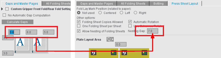
If Signa Station detects during automatic placement in the "Imposition" mode that the number of folding sheets that can be placed with and without rotation is identical, then the rotated variant (90 degrees) is used if this option is enabled.
Number Folding Sheets (gang run form only)
Defines how many folding sheets of the same kind will be placed on the press sheet.
List box (1up, 2up, 4up, 8up) (gang run form only)
The folding sheet 1ups are increased by the number you select. 1up is set by default.
Edit Table (gang run form only)
You can change the positions of the folding sheets manually in X and Y direction. You can change the orientation of the folding sheets clockwise by 90° in a list box. Use the "swapped" option to position folding sheets from the front to the back and back again.
Lets you load a resource from the "Plate Layout" section.
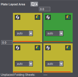
Each colored element marks a folding sheet.
The red line refers to the fold lay mark.
The yellow folding sheet indicates that the front of the folding sheet is on the front of the press sheet.
The green folding sheet indicates that the back of the folding sheet is on the front of the press sheet.
Input box(es)
You can define free spaces between the folding sheets.
Folding sheets rotated (button)
This function is required if you wish to change the orientation between several folding sheets. The fold lay marks are rotated by 180° when you click this button.
Swap front / back (button)
In practice, you generally want to use the separating line as the lay mark for the folder if you have more than one folding sheet. This is only possible if you can place normal folding sheets together with folding sheets with swapped front and back on one press sheet.
Auto (list box)
The "Auto" list box controls the order of the folding sheets on the press sheet.
The first folding sheet is always at the bottom left in an automatic arrangement.
To change the order to suit your needs, you must define all the list boxes correctly (no number twice, no "Auto").
Unplaced Folding Sheets:
All folding sheets must be included if they are not to be placed automatically.
Parameters for Ganging Optimization
You can define which folding sheets are intended for ganging. This requires the "Gang & Sheet Optimizer" license.
For this purpose, enable "Ganging Intended" in the "Press Sheet Layout" tab. Then, during a JDF output, all folding sheets that are derived from this scheme have a special marking. You can then use this marking to submit these folding sheets automatically to ganging. The option is not available for folding sheets on gang run forms ("Ganging Optimization" work mode).
You can define the orientation on the paper with "Orientation Default". With "normal" and "rotated", you specify the orientation related to the paper for all 1up copies of this article. With "uniform", optimization determines the better of the two variants for utilization of the sheet. In this process, all 1up copies of the article have the same orientation; this means that either they are all rotated or none are rotated. If you select "none", orientation is ignored and only the best possible utilization of the sheet is considered. In this case, it is possible that some 1up copies of the article are rotated and some are not. This can be a good idea in the case of articles where the grain direction of the paper is irrelevant or for materials without grain direction.
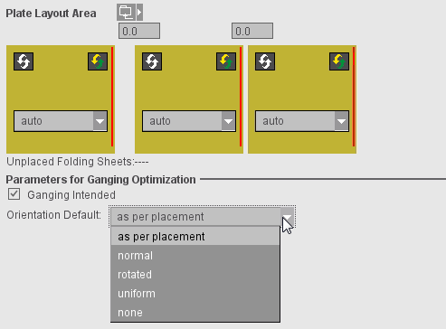
The "Section Handling" tab is used only for the twin lay option. A 'section' essentially describes a folding sheet with one scheme. In the twin lay mode, however, you can split a scheme into two sections that look like separate folding sheets for the rest of the system.
The table shows the folding sheets placed on each of the press sheets.
For twin lay, you can divide a scheme into an "inner" and an "outer" half. The "Type/Version" column shows this as the section "type".
The "Section Setup Editor" opens when you click "Change Section Order...".
The table shown in the editor is structured like the table in the "Section Handling" tab but shows only a copy of the current state.
•"Double Section": Each scheme is split into two sections. The number of active sections is doubled, the result is reflected in the page count. When automatic collating marks and/or sheet labels are active, they will be set according to the section numbers.
If "Double Section" is used and the system detects that the page count set in the product part will only fit if the last scheme will be used as a double 1up, this will be matched automatically. Example: 144 pages and five 32-page schemes. In this case, the same section is assigned to the last scheme twice if "Double Section" is used.
•"Double Section (Selection)": If four 32-page schemes and one 16-page scheme are used for 144 pages, you can then select which schemes are to be divided into two sections. The "Double Section (Selection)" functions assigns two sections to all selected folding sheets and one section to the non-selected folding sheets.
•"Single Section": Every folding sheet contains the complete scheme.
•"Calculate Section List": The values in the "Folding Sheet" column can be edited. To do so, click on a field of the column and enter the desired section number.
After editing, you must press the button "Calculate Section List" because it is quite natural that inconsistent intermediate results occur. The list is then checked for consistency (no numbers must be missing), and the new section list is generated.
To undo sections for certain folding sheets, specify "0" for the "Inner" section of this folding sheet. You can also make double 1ups by assigning the same section number to both sections of the scheme. With this tool, you can collect the sections on a single press sheet, e.g. to print them together because of the color used.
•"OK": The changed data will be imported into the product part
•"Close": The Editor closes without saving the original data
There is another way of resorting sections: you can swap two sections with drag&drop. You can do this here in the Editor table but also in the Inspector table.
Automatic gap computation makes sure that folding sheet margins and gaps are matched automatically to fit the maximum number of folding sheets on the paper and at the same time that the folding sheets together take up as much of the whole printing material size as possible, making as few cuts as possible necessary. This takes into account the set binding method. For example, for "Loose Binding", the spacing between the pages is evenly distributed; in saddlestitching, there is no spacing between the pages in the back margin.

Note: In Automatic Gap Computation, the head and foot trim are calculated separately and asymmetric trims are generated if this would make the folding sheet margins extend to the paper margin.
Example with saddlestitching:

There are different options for running calculation:
1.In the "Binding" step, you can enable automatic gap computation as a set option for the product part. This setting makes sure that, if changes are made in the product part, automatic gap computation is run again.
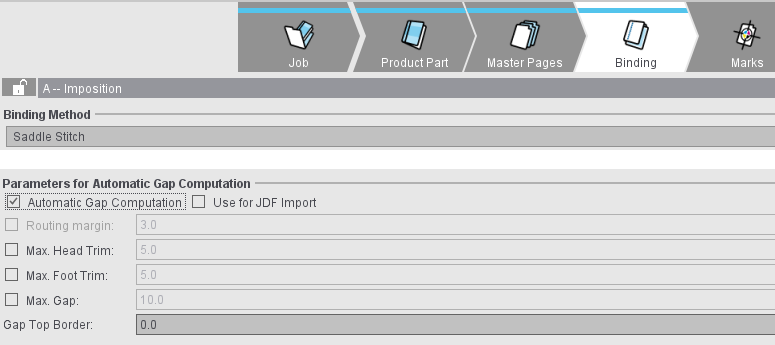
2.In the "Schemes" step, single schemes can be excluded from this automatic mode (1).
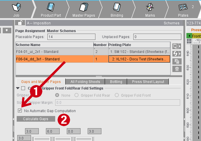
3.You can manually run gap computation using the "Calculate Gaps" button (2) in the "Schemes" step. The button is active when the automatic mode is switched off in the "Binding" step or the current scheme is excluded.
4.For a JDF import without a product part template, you can enable automatic gap computation in the Preferences. This setting then makes sure that automatic gap computation is enabled in the "Binding" step in the product part created.
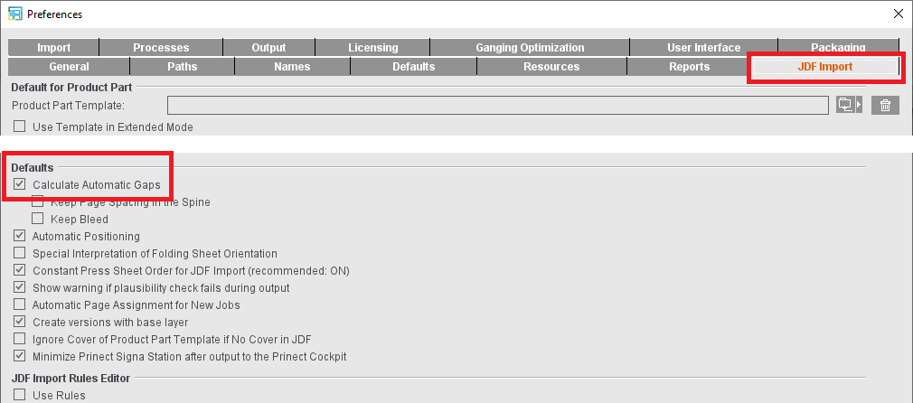
5.For a JDF import with a product part template, you can set in the product part template which setting will be used. The "Use for JDF Import" option is available in the "Binding" step. When this option is enabled, the setting for automatic gap calculation from the product part template will be used. If not, the setting from the Preferences is used.
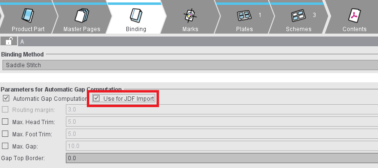
The calculated margins and gaps are made up of two parts. A static part that is permanently entered and a dynamic part that depends on the available space and constraints that can be set. The two parts are added up.
Static part
Trim Allowance
In the "Master Pages" step, you can define additional margins for all master pages. "Inner" refers to the margin in the back margin, "Outer" to the opposite margin and "Top" and "Bottom" to the top and bottom margins of the page.
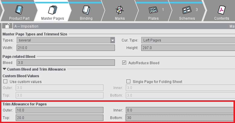
Gripper Collator (front/rear fold)
An outer additional margin is needed on all pages either before the center fold (front fold) or after the center fold (rear fold) so that saddlestitcher can grip a folding sheet in such a way that the folding sheet opens in the middle and is placed correctly on the line. This margin can be set in the "Binding" step. When this setting is enabled, a margin in addition to the "Outer" trim allowance defined in the master page is added on all pages before or after the center fold.
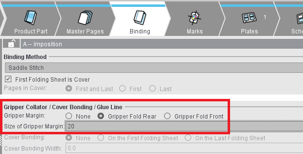
Dynamic part
You can define settings for the dynamic part of gap calculation in the "Binding" step.
Maximum head trim
If this option is active, the margins or gaps at the top of the page are only enlarged by the maximum value set. If possible, the remaining space will be spread over the foot trims. Limiting the head trim may be necessary for saddlestitchers and perfect binders that align the folding sheets along the head. This setting together with "Maximum Foot Trim" or "Maximum Gap" may result in a situation where all of the available area cannot be utilized.
Maximum foot trim
Similar to the maximum head trim for restricting the foot trim. Required for saddlestitchers and perfect binders that align the fold sheet on the foot. This setting may also result in all of the available area not being utilized to the full.
Maximum gap
Limits the dynamic part of all margins and gaps. Unless explicit values for maximum head trims or foot trims were set. This setting may also result in all of the available area not being utilized to the full.
Minimum head trim/foot trim/gap
If one of these options is enabled, the trim values are increased at least to the set value. As with the maximum values, the value for the gap is also used for the head and foot trim unless other values are explicitly specified.
The minimum value must be less than or equal to the maximum value. If the minimum and maximum values enabled at the same time contradict each other, the values are displayed in red and the maximum values are used for the calculation.

Note: If the specifications for the gap calculation contradict the settings for the subject positioning in the "Plates" step, the values from the "Plates" step are used and the fields for the gaps in the "Binding" step are highlighted with warning icons. The tooltip for the warning icon provides tips on the reason and possible effect.
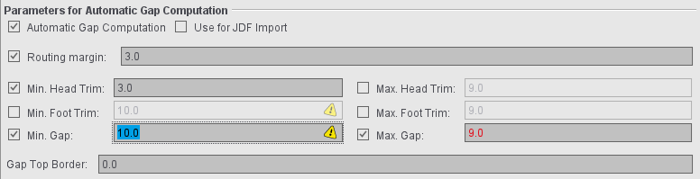
Gap Top Border
If a positive value is entered in this box, gaps and margins of the folding sheets are enlarged only to the extent that an area still is not used at the top of the press sheet.
Consider Gripper Margins and Non-Printable Margins
Another setting that can impact gap computation is in the "Plates" step. The "Include Gripper Margins and Non-Printable Margins" option makes sure that the page content is not in the non-printable area. In some circumstances, this can only be achieved by not pushing the margins and gaps to the edge of the paper.
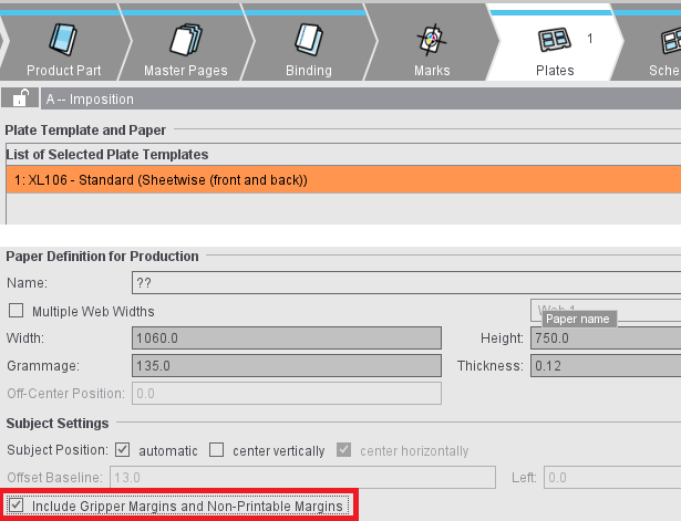
Preferences
For new product parts, you can define the setup for gap calculation in the Preferences:
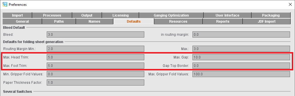
Assembly Block (only in the "Montage" work mode)
The "Assembly Block" step is designed to edit jobs you created in the "Montage" work mode.
In this group, you can create, position and delete assembly blocks and load a CFF2 file as a single 1up.
This displays the block name (that you can edit) that is selected in the Browser window or in the graphic view. You can enter a prefix for all the block names if you haven't selected a block name. You can change the name afterwards.
You can create a new assembly block by clicking the icon below.

Click the folder button below to load a CFF2 file for creating a new assembly block with a CAD single 1up. You can then duplicate and arrange the 1up as you want. You can edit the clip path in the "Folding Sheet/Assembly Block/Cutting Die" tab in the graphic window. See Packaging (Packaging Pro, Label Pro).
The option is only available if the "Packaging" option is enabled.

You can delete the assembly block from the list by clicking the trashcan icon.

Width/Height
The size of the 1up is specified.
The bleed width is shown. Signa Station makes sure automatically that bleeds do not overlap in an assembly bock.
Name
You can fully rename the selected assembly block (with single 1ups). This is a fast way to assign unique names if there are different 1ups. The changed name is taken into account in the JDF workflow.
Enable "Use custom values".
You can define a custom bleed for all the pages of the selected 1up.
Orientation
You can rotate the 1ups on the selected assembly block by the specified degrees with this option.
Click "On". You can then enter an angle by which the 1ups on the selected assembly block will be rotated. Pivot is bottom left. This is used for envelopes, for example, to align the rear flap of the envelope correctly (35°).
Placement rule for assigned 1ups
You can find a description of this in Placement rule for assigned pages.

Note: In the Assembly Block Template Editor, there are also settings to mark the assembly block for submitting it to ganging.
See details in Parameters for Ganging Optimization
When this option is set (default), all the 1ups are assigned the same content. In the graphic window, you will see that all the 1ups have the same number. The 1ups of the first assembly block are all numbered "1", those of the second assembly block "2", etc. When you assign the content of a 1up to an assembly block, all the 1ups in this assembly block are automatically given the same content.
The 1ups are numbered consecutively, starting with one ('1'), if the option is not set. In this case, you must assign the contents separately for each 1up.
In these boxes, you can define how often a 1up in the assembly block will be created in X (horizontal) or Y (vertical) direction.
Fill sheet
Starting from the present position of the assembly block on the press sheet, as many 1ups as will fit on the press sheet will be created to the right, left and/or on top.
If an assembly block has several 1ups, you can specify the gaps between the 1ups in X and Y direction.
Position X/Y
This shows the position of the selected assembly block on the press sheet. The bottom left corner of the paper is the zero point for both directions.
Margin, left / right / top / bottom
You can enter a margin for the assembly block in these boxes. A cut mark is not placed if this margin is smaller than the cut mark. This allows the cut point for assembly blocks to be set accurately without the automatically set cut marks disturbing this setting.
In lenticular printing, a lens foil and a specially edited 1up (image) are needed for impositioning. The lens foil is printed from the back and consists of parallel lenses (curvature of the foil). In addition, you have to set other conditions for assembly:
Lenticular Scaling
Different lenticular effects need either a horizontal or vertical orientation of the lens.
Mechanical Pitch (resolution of the foil): Describes the resolution of the foil.
Image Scale: Matches the image to the recorder resolution.
Parameters for Ganging Optimization
This requires the "Gang & Sheet Optimizer" license. You can use this marking to submit these assembly blocks automatically to ganging.
You can define the orientation on the paper with "Orientation Default". With "normal" and "rotated", you specify the orientation related to the paper for all 1up copies of this article. With "uniform", optimization determines the better of the two variants for utilization of the sheet. In this process, all 1up copies of the article have the same orientation; this means that either they are all rotated or none are rotated. If you select "none", orientation is ignored and only the best possible utilization of the sheet is considered. In this case, it is possible that some 1up copies of the article are rotated and some are not. This can be a good idea in the case of articles where the grain direction of the paper is irrelevant or for materials without grain direction.
You can set an orientation default for the single 1ups with "Orientation Default for LabelPro" (only with the "Label Pro" license). The value for the orientation default then displays in the Nesting Wizard of LabelPro.
You can find a description of this in Marks.
Difference to above description: In contrast to the Folding Sheet Inspector, you can only change the automatically set cut marks in the Assembly Block Inspector but not the folding marks, collating mark, folding crosses and folding sheet cuts.
You can find a description of this in Marks Resources .
Packaging (only in the "Packaging" work mode and in "Sheet Optimization for Packaging")
The "Packaging Pro" and/or "Label Pro" license is a prerequisite in Signa Station for the "Packaging" step. We will explain the functionalities in this step in the sections below.
You can find a description of how to work in the "Packaging" work mode in Packaging (Packaging Pro, Label Pro).
Cutting Die File and Main Settings
The table shows all loaded cutting die files with file name, tool and format. You have the option of changing the tool ID in the "Tool" box.
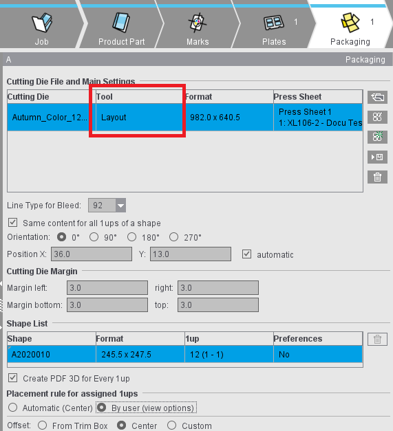
Notes on the table
"Press Sheet" column
The "Press Sheet" column indicates the press sheet and the related plate template on which the cutting die is placed.
In the "Sheet Optimization for Packaging" work mode: "Sheet Layout" column
This column displays the set sheet layout that the cutting die is assigned to.
The term "sheet layout" describes the combination of plate template and the number of cutting dies placed on the press sheet resulting from this plate template.
You can undo an optimization process that was run using the button at the bottom right edge of the table. This makes it possible to restore the situation before optimization (quantity of sheet layouts) as this can change fundamentally after an optimization. The button is enabled after an optimization process is run.

Note: The sheet layouts used display with plate and paper in the "Press Sheet" table in the "Results" step and in the HTML report.
Context menu
•"Duplicate Cutting Die"
Existing cutting dies can be duplicated via the context menu and added to the table. All properties of the source cutting dies are transferred to the newly created cutting dies. Multiple selection is possible. The newly created cutting dies are arranged below the respective source cutting die in the table and selected directly.
•"New Press Sheet" or "New Sheet Layout"
A new press sheet or a new sheet layout based on the appropriate plate template is generated and the selected cutting dies placed. The default position setting of the plate template is always used when a new press sheet/sheet layout is being generated.

Note: The "New press sheet" entry can only be selected if this action results in a change to the assignment of the selected cutting dies to the press sheets or sheet layouts. This is the case if all selected cutting dies are not on the same press sheet or if there are other cutting dies on this press sheet.
•Press sheet or sheet layout selected
The selected cutting dies are moved and placed on this press sheet or sheet layout as specified in the position setting. Any empty press sheet or empty sheet layout (without cutting dies) resulting from such an action is deleted automatically.
•"No Press Sheet" or "No Sheet Layout"
Assignment of the cutting die to a press sheet or sheet layout is deleted.
A dash displays in the "Press Sheet" or "Sheet Layout" column if a cutting die is not assigned to a plate template. If a plate template is deleted, the assignments of cutting dies to this plate template are also deleted.
"Positioning of Cutting Dies" column
The "Positioning of Cutting Dies" column shows the positioning of the cutting die analogous to the positioning buttons in "Plates" (see Points to note for "Plates" in the "Packaging" or "Sheet Optimization" mode). This setting refers to the press sheet. In other words, this value is valid for all the cutting dies placed on a press sheet.
In an automatic placement, the icon displayed is similar to that selected in the "Plates" step. This setting changes to "manual" (hand) if a cutting die is moved manually in the graphic view or if its position values are changed. You can edit the position setting of the press sheet in the context menu on this column. The placed cutting dies are positioned as indicated in this setting.
Button functions

|
Folder button |

|
PackagingPro button |

|
LabelPro button |

Note: The following requirements must be met to be able to use the LabelPro button:
- There must be at least one plate template in the product part
- No other cutting dies are open
- For all plate templates, positioning of the subject is set to whole sheets (see Subject Settings (positioning of the cutting dies))
In the "Ganging Optimization" mode:
- There are items in the "Input List for Sheet Optimization"
- A shape is set for all these items
In the "Packaging" mode:
- Documents with content are in the job.

|
Save CAD file |

|
Save CAD file to AutoToolPool |

|
Trashcan button |
•It is also possible to set a default folder for CAD files in "Preferences > Packaging" if you are working with cutting die files.
You can also load a cutting die file with drag-and-drop. See Drag-and-Drop for details.
Apart from details about the files, the table also displays all contours of the cutting die in the "Contours" column (number of contours in brackets), and in the "Relevance" column a percentage indicating how well the cutting die fits the contours demanded by the Multiple Sheet Optimizer (only if the Multiple Sheet Optimizer is enabled).
You can also view the shape by selecting the related tab above the preview window.
In the "Line Type for Bleed" list box, you can select the line types available for the selected cutting die.
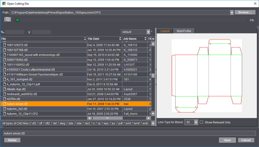
Besides the most frequently used files of type CF2, CFF and CFF2, you can also load or import other types of CAD files as cutting dies. Basically, there are three different procedures when opening the cutting die file:
·Cutting die files of type *.cff, *.cf2 and *.cff2 that were created, for example, with Package Designer or ArtPro.
You can load these files directly to Signa Station. You only have to open a correct CFF2 cutting die with Packaging Pro if you want to create a PDF 3D or specify the trim on the sheet layout.
·Cutting dies of type *.evd created with Package Designer
You can also load these files in Signa Station directly without automatically starting Packaging Pro and without requiring manual intervention. This means that evd files can also be processed in automated workflows. The evd files can be linked in an MIS-JDF or Multi-GangPart-XML. The prerequisite is that the evd files are saved in the specified network folder with the correct name. The result is a cutting die file of type "evd" if all contours of a job are available in evd format. A cutting die file in cf2 format is generated for mixed jobs.
If an EVD file contains several layouts, the "Open Cutting Die" dialog automatically appears when the file is opened in the "Packaging" step. All the layouts contained are displayed here and you can select the desired layout. If the EVD file is imported using drag & drop, the "Select Layout" dialog for opening the desired layout appears automatically.
·Other vector-based formats like, for example, AutoCAD files of type *.dxf or *.dwg, *.ai files created with Adobe Illustrator, DieCAD files (*.n), DDS (*.dds, *.dde, *.ds2), PDF, EPS/PS and Windows meta formats (*.wmf, *.emf)
Here, too, Packaging Pro launches automatically for the import. You first see the "Import Preview" window where you can set various filters for the import, for example, which line types will be assigned to cutting, creasing, etc. After the import, the die first displays in Packaging Pro where you can revise and correct data (e.g. incorrectly defined line type) and create the layout for the sheet.

Note: You will find details about these topics and working with Packaging Pro and Label Pro in their respective Online Helps that you invoke with the F1 key from that option or using the Help menu in Signa Station.
In the graphic window, the hulls of the loaded cutting die file have green lines.
Line Type for Bleed
The default value is "92".
All the lines of this type in the cutting die file are considered bleed lines. This should produce a closed path.
In the "Sheet Optimization for Packaging" work mode: "Order of Indices"
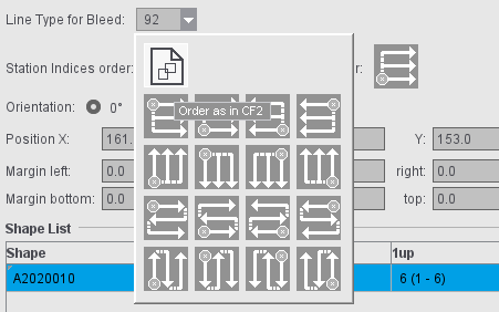
By default, the order of indices as set in the CF2 file is used. You can choose another order as the default for each cutting die by clicking the icon. The change immediately displays in the graphic window; repeating the optimization is not necessary. You can change the setting in the "Packaging" tab if a certain order is to be used by default.
In the "Sheet Optimization for Packaging" work mode: "Order of Station Numbers"
In "Preferences > Packaging > Order of Indices and station numbers" you can set the default order of station numbers. This presetting is effective when creating new jobs/job templates or product parts/product part templates in "Packaging" and "Sheet Optimization for Packaging" mode.
In the "Ganging optimization > Sheet Optimization for Packaging" mode, the sequence of the station numbers can also be specified directly in the "Packaging" step. This step is initially assigned the order of the station numbers from the default settings. If the sequence of the station numbers is changed, this has an immediate effect - without new optimization. When importing MIS JDFs, the order of the station numbers from the default settings is used.
Same Content for All 1ups of a Shape
When this option is set, a hull (shape) is automatically assigned the same content. In the graphic window, you will see that all the hulls have the same number.
The numbers are incremented if the option is not set and if a hull has different content. In this case, you must assign the contents separately for each hull.
The cutting die selected in "File" is rotated counterclockwise by the selected angle on the paper.
Manual positioning is possible using "Position X" and "Y".
In addition, you can use the four buttons to position the cutting dies horizontally or relative to the center of the paper (useful when working with a separating cut) and vertically or with the gripper margin. Positioning relative to the center is useful when working with a separating cut and is available only if multiple cutting dies are loaded.
By enabling the "automatic" option (to the right of the position values), the subjects are arranged according to the template in the "Plates" step (see Subject Settings (positioning of the cutting dies)). This setting applies per press sheet and therefore for all cutting dies that are placed on the same press sheet.
You can specify margins for cutting dies. By default, the values predefined in the Preferences in "Packaging" for the four margins (left, right, bottom, top) are applied to the job.

Note: In the case of cutting dies from program versions that do not support margins, the margins of these cutting dies will automatically be set to "0".
There are two different cases in the positioning of cutting dies:
•Jobs with all margins in all cutting dies with the value equal "0":
The cutting dies are positioned on the available space, evenly distributed.
•Jobs with at least one margin of a cutting die with a value unequal "0":
The cutting dies are positioned directly side by side taking into account the margins.
You can find examples for positioning in Positioning of Cutting Dies Depending on Work Style and Margin
Table showing the hulls of a cutting die file.
Each hull displays its name, styles (geometry data), number of 1ups and the defined presettings.
You can rename a hull manually and delete a selected one.

|
You will see the trashcan to the right of the table. You can use this to delete hulls that are no longer needed from the table. Deleted hulls are no longer shown in the graphic window. |
For jobs with front and back printing, the trim paths can be set differently for each shape. To do this, you can toggle the "Bleed" column for each shape in the list of shapes (1: Bleed is identical for front and back printing; 2: Bleed can be different for front and back printing):
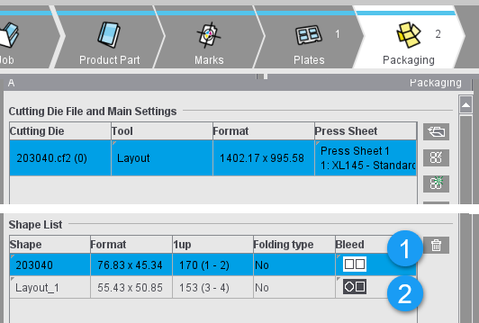
If identical bleed is set (1), changes made with the Clip Path Tool (see description under "Feather"-button tool) are automatically transferred from the front to the back and vice versa.
If different bleed settings are allowed (2), the clip path of one shape can be manually changed without affecting the clip path on the other sheet.
If the setting is switched to "identical" for a shape with different clip paths, the clip path of the front side is adopted.

Note: This is also possible in Packaging Pro. While only individual components can be edited in Signa Station, in Packaging Pro you can either work on individual shapes within the layout or edit the shape itself, thereby applying the changes uniformly to all shape of that type in the layout.
An accurate preview is calculated for each 1up (with all existing marks) when this option is enabled. You can disable it to save time when saving your data. In this case, a preview is created only of the first 1up.
Placement rule for assigned 1ups
This is where you define the placement for all the 1ups of the selected hull. The default in the "Packaging" mode differs from that in "Imposition" "By user" > "Center".
Positioning of Cutting Dies Depending on Work Style and Margin

Caution: If the subject setting is set to half sheet positioning and if a work style that does not support half sheet positioning is selected when switching to it, the system automatically switches to the appropriate full sheet positioning.
"Single-sided (no back)" or "Perfecting" or "Sheetwise (front and back)" work styles
|
Positioning |
All margins equal 0 |
At least one margin unequal 0 |
|---|---|---|
|
|
evenly distributed in horizontal direction |
side by side in horizontal direction |

The cutting dies are centered vertically on the paper. |
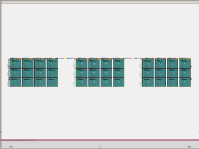
|
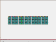
|

The cutting dies are positioned vertically on the gripper margin on the paper. |
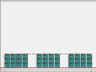
|
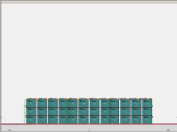
|
|
Depending on the height of the margin, the cut blocks or the bleed of the cutting die are positioned on the gripper margin, in the same way as for the "Imposition" mode. |
||

The cutting dies are positioned vertically on the paper with a variable offset to the lower paper edge. |
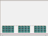
|
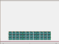
|
|
Depending on the height of the margin, the cut blocks or the bleed of the cutting die are positioned on the set offset to the lower paper edge. |
||

The cutting dies are positioned vertically on the paper with a variable offset to the lower paper edge and horizontally with a variable offset to the left paper edge. |
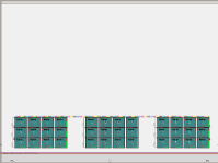
|
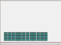
|
|
Depending on the height of the left or lower margin of the cutting die, either the cut blocks or the bleed of the cutting die are positioned on the set offset to the left or lower paper edge. |
||
|
|
evenly distributed in vertical direction |
side by side in vertical direction |

The paper is cut through the vertical center and the cutting dies on both halves of paper are positioned on the horizontal center. |
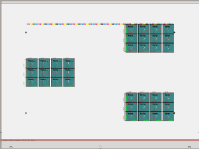
|
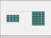
|

The paper is cut through the vertical center and the cutting dies on both halves of paper are positioned horizontally on the "cut" margin on the left and right. |
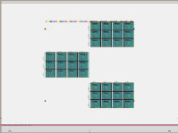
|
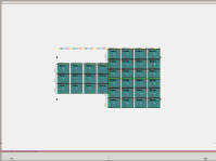
|
|
Depending on the height of the left or lower margin of the cutting die, either the cut blocks or the bleed of the cutting die are positioned on the gripper margin, in the same way as for the "Imposition" mode. |
||
"Work-and-turn" work style
|
Positioning |
All margins equal 0 |
At least one margin unequal 0 |
|---|---|---|
|
|
evenly distributed in vertical direction |
side by side in vertical direction |

The cutting dies are positioned horizontally on the paper on the "work-and-turn edge". |
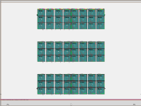
|
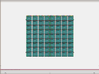
|

The cutting dies are positioned on the paper horizontally on the "work-and-turn edge" and vertically on the gripper margin. |
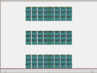
|
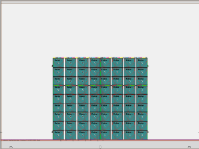
|
|
Depending on the height of the margin, the cut blocks or the bleed of the cutting die are positioned on the gripper margin, in the same way as for the "Imposition" mode. |
||

The cutting dies are positioned on the paper horizontally on the "work-and-turn edge" and vertically with a variable offset to the lower paper edge. |
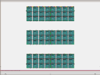
|
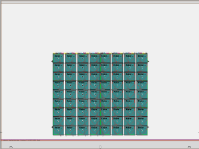
|
|
Depending on the height of the margin, the cut blocks or the bleed of the cutting die are positioned on the set offset to the lower paper edge. |
||

The cutting dies are positioned on the paper horizontally with a variable offset to the left paper edge and vertically with a variable offset to the lower paper edge. |
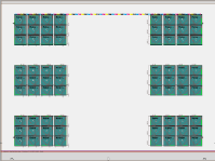
|
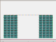
|
|
Depending on the height of the left or lower margin of the cutting die, either the cut blocks or the bleed of the cutting die are positioned on the set offset to the left or lower paper edge. |
||
|
Positioning |
|
|
|---|---|---|


|
Half sheet positioning is not supported in "work-and-turn". |
|
"Work-and-tumble" work style
|
Positioning |
All margins equal 0 |
At least one margin unequal 0 |
|---|---|---|
|
|
evenly distributed in horizontal direction |
side by side in horizontal direction |

The cutting dies are positioned vertically on the "work-and-tumble edge" on the paper. |
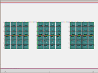
|
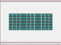
|

The cutting dies are positioned vertically on the gripper margin on the paper. |
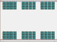
|
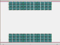
|
|
Depending on the height of the margin, the cut blocks or the bleed of the cutting die are positioned on the gripper margin, in the same way as for the "Imposition" mode. |
||

The cutting dies are positioned vertically on the paper with a variable offset to the lower paper edge. |
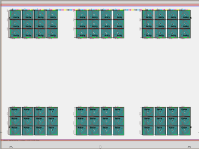
|
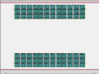
|
|
Depending on the height of the margin, the cut blocks or the bleed of the cutting die are positioned on the set offset to the lower paper edge. |
||

The cutting dies are positioned on the paper horizontally with a variable offset to the left paper edge and vertically with a variable offset to the lower paper edge. |
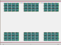
|
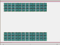
|
|
Depending on the height of the left or lower margin of the cutting die, either the cut blocks or the bleed of the cutting die are positioned on the set offset to the left or lower paper edge. |
||
|
Positioning |
|
|
|---|---|---|


|
Half sheet positioning is not supported in "work-and-tumble". |
|
Article (only in the "Packaging" work mode)
The "Article" step is available in the "Packaging" work mode if you work without ganging optimization.
The "Article" step contains a table with the articles of all press sheets and cutting dies.
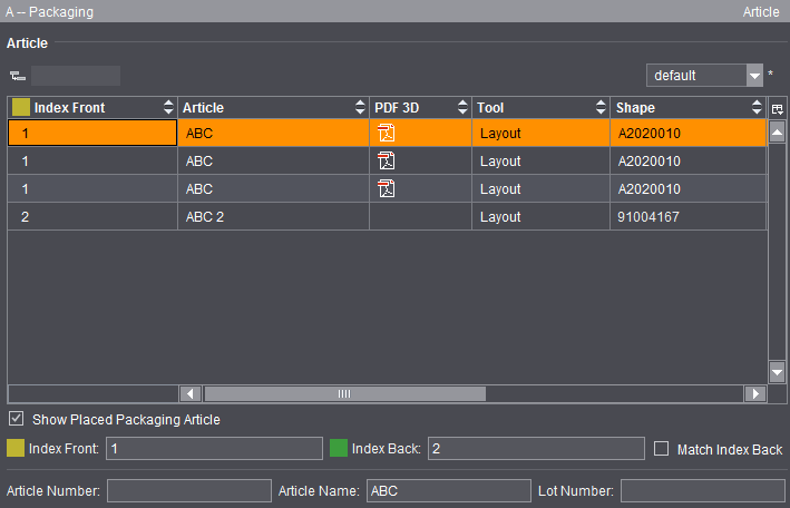
The table is implemented as a grouping table. Consequently, a flat and a hierarchical display of the contents are possible. The boxes below the table let you edit index, lot number and article designation (made up of article name and number) for the selected row (multiple selection possible). Alternatively, you can also invoke the related edit dialog using the context menu (right-click one of the columns "Index Front", "Index Back", "Article" or "Lot Number"):
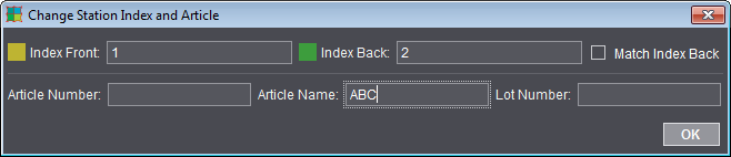

Note: You can invoke this dialog also directly in the graphic window using the context menu.
The table of articles has the following columns:
•Index Front
•if necessary, Index Back
Use the checkbox below the table to match the index for the back automatically to the index for the front.
•Article
•PDF 3D
The name of the PDF 3D comprises:
·Article name (if any) or 1up name (if any) or name of the cutting die file
·Index of 1up front
·Product Part Name
·"3D" and an internal counter
•File
•Tool
•Shape
•Lot Number
•PDF File (assigned PDF file for the related article)
•Sheet
A PDF icon displays below "PDF 3D" after you finish editing in the "Signa Station Packaging Pro" Editor. A three-dimensional view of the generated article displays in Adobe Acrobat or Adobe Reader when you double-click the icon:


Prerequisite: The PDF 3D format requires Adobe Acrobat or Reader version > 9 to display the data and use the features properly.
In the PDF 3D you can view the 1ups with their printed data folded out or as a finished carton that is folded. You can view the folding process in various animation steps and scale, move and rotate the object.

Note: In some cases, inner and outer panels may not be displayed correctly if these are in one layer (see page fold on the figure above). You can correct the display by specifying a slightly larger angle for this fold in Packaging Pro (the fold concerned is effectively folded one more time).
The step is enabled for a gang job only with the "Gang & Sheet Optimizer" option (see also Ganging Optimization).
When you have a gang job, you can set various parameters for optimal distribution of the 1ups on the press sheets in the "Optimization" step.
These parameter values are then used to calculate the position of the 1ups/articles and the number of required press sheets taking into account the geometry data and the quantity (part of the xml or csv file).
Optimization is based on geometric variables like sheet margins and paper size and also includes cost-related parameters.
The results of optimization display in detail in the "Results" step. You can only start a new optimization in this step or open the HTML report for optimization.
In addition to the results already shown in the "Optimization" step, you can view all other details of the analysis (1) as also found in the HTML report.
On the one hand, the tables display an analysis of the press sheets as per the rating criteria defined for optimization (2) and on the other a list of placed articles with details about delivery quantity, overproduction, waste, etc. (3).
See "Rating" Tab for a description of the press sheet details and rating.
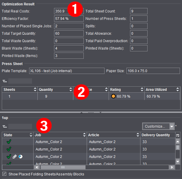
In the "State" column, you can view the latest details about placement of all articles after each optimization run:
|
|
The article is optimized and placed on one or more press sheets. |
|
|
The article was not placed on one of the press sheets because it was set to "inactive". |
|
|
The article was not placed. There may be several reasons for this, like for example, the poor rating of a press sheet. You will find more details about the icons in Input List for Sheet Optimization (grouping table). |
The "Contents" step with its two sections, "Contents" and "Document Inspector", imports PDF and PS files to the job currently open on the one hand and on the other assigns the pages found in the files. In addition, the key data of the imported file and the properties of the single pages are displayed.

Note: Remember that the "Contents" step is valid for the whole job. You can place PDF files, for example, on several product parts of the job.
You can import the data to one or more layers.
You start the import of PDF and PS files in the "Contents" step using the context menu in the "Contents" section. You will find a description of the "Document Inspector" section in Document Inspector .
You can drag-and-drop PDF files or pages from the "Contents" section to the graphic window. These are then automatically placed on plates, pages of the job currently open. You can find more details about drag-and-drop in Drag-and-Drop.
An alternative means of import is to use drag-and-drop from the operating system. See Drag-and-Drop for details.
•You can import PDF and/or PS files to the job currently open in the "Contents" section. Display the context menu, click "Documents" and select a PDF or PS file.

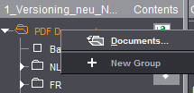
•Import of PDF files to a number of layers for positioning by dragging-and-dropping them to the "Contents" section.

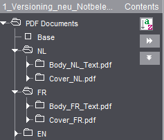
•After the import, you can assign the pages in the PDF file to the open job (with drag-and-drop, see Drag-and-Drop). The pages in the PDF file are shown as a list. In the screenshot below, you can see that the PDF file has an assigned page in the job. However, the PDF file in "FR" is not yet assigned to the job.

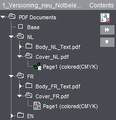
•A double click on imported pages opens the "Document" tab in the graphic window and their data display in the Document Inspector.
•The following functions are found in the context menu when a PDF file or pages are selected:

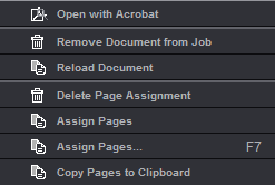
•"Open with Acrobat"
The whole PDF file is opened and displayed with Acrobat. See also Select External Executables.
•"Remove Document from Job"
The document you selected is deleted from the job.
•"Delete Page Assignment"
Deletes assignment of the selected page(s)/1up(s) in the job. The pages/1ups in the job no longer have any assigned content.
•"Assign Pages"
The selected pages are assigned to the job. The pages/1ups are assigned automatically to the next blank pages in the job.
The Assistant that helps you assign pages displays. The Assistant shows you the position and layer of the assigned PDF file and makes it easy for you to assign PDF files to the job. It also makes it easy to replace pages later, for example, from correction PDFs.
The Assistant for assigning pages is recommended mainly for extremely large jobs, jobs with several layers and/or for jobs with versions.
When a PDF document is selected, you can start the Assistant either using the context menu or with the F7 key. Invoking the Assistant with the F7 also works if the layer is selected.
In the case of jobs with several layers, you can toggle the open Assistant by marking a different layer in the tree structure of the "Contents" section. The Assistant for assigning pages stays open when you select a different document in the tree structure and it switches automatically to the layer or assignment table you selected. It is possible that the window may go to the background in this process. For that reason, we recommend placing the window of the Assistant beside the main window or on a second screen.
When you click "Apply", the assignment as set in the assignment table is applied and displays in the graphic view.
In this process, you can select in the list whether all positions will be assigned or, for example, only even or uneven ones. When you select "User-defined Range", you can define custom assignments in the "Start from" box by specifying position ranges, adding via commas or grouping in parentheses. Example: 1-6,7,(9,12).
Example: For an 8-page document with a base version and three language versions, you receive a PDF with three pages to be replaced in the base version, e.g. modified background graphics.
Procedure:
1.In "Contents", mark the base and add the PDF document.
2.Mark the document and press F7 to invoke the Assistant for assigning pages.
·The last three pages (= 6 thru 8) are to be replaced: Select "All Positions", "Start from: 6" (example A)
·Single pages are to be replaced, e.g. pages 4, 5 and 8. In this case, enter the numbers of the pages to be replaced, separated by commas, as the user-defined range: Select "User-defined Range", "Start from: 4,5,8"
·The first page from the correction PDF is to be used for all pages from 2 thru 6. The other two pages are to replace the last two pages: Select "User-defined Range", "Start from: 2-6,7,8" (example B)

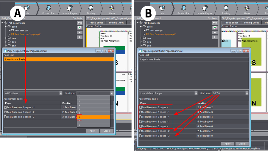
•"Copy Pages to Clipboard"
The selected page/1up is copied to the clipboard and can be pasted at any place you want, for example, in the graphic window in the "Page List" tab. See also "Paste Pages from Clipboard".
You can find the Document Inspector in the "Contents" step. It displays by default, but you can also minimize it using the arrow on the border.
This provides you with general information about the document currently selected in the "Contents" section.
Properties
The properties of the selected PDF document are shown. The information comes from the layout application.
The colors used in the entire document, including spot colors, are shown in this list.
If you are working with separated PDF, you can change the color names in the table by double-clicking the table item. The new name is then used in the job.
Only available if a PDF file with variable data is loaded in the job. You load a PDF-VT file in the usual way in the "Contents" step.
All the data sets of a PDF-VT document display in the Document Inspector.
For output of a PDF-VT file, see Press Sheets .
No. of Records
Shows the number of data records (pages) in the file.
Current Data Set
Text box indicating the data record in the graphic view.
This provides you with information about the PDF page you have currently selected. It is also possible for you to modify or move the trim box of the PDF page.
Area of application
This parameter lets you define where the changes will be applied if changes are made.
The default setting is "selected". The selected page and PDF file are shown in the caption bar of the window.
You can also select "even" where all even pages will be changed, "odd" for changes to all odd pages and "all" where all pages of the selected PDF file will be changed.
If you select "all", each change will be applied at once and without confirmation to all the pages/1ups in the PDF file. You can view the changes right away in the "Document" tab in the graphic window.
Selection
The list box shows the bounding boxes defined in the PDF file. Only different sized boxes are shown.
The trim box always forms the basis.
If you select a larger media box, for example, this is used as the basis for offsets. The selected media box becomes the trim box.
The list box changes to "user-defined" if you change the values below because changing them means that they are inevitably different to those of the trim box.
Rel. position X/Y
This option lets you move the trim box relative to the content of a PDF page. As a result, the motif can be in a different position in the trim box. The bottom left corner is the reference point.
This can be used in PDF page assignment if the following setting was selected for the master page in the "Master Pages" step > "Placement rule for assigned pages/1ups":
•"Automatic" mode or
•"By user (view options)" mode with "From trim box" offset.
A change in the size of the trim box ("Document" tab in the graphic window) does not affect positioning. Only the position of the bottom left corner is important.
You can use offset accurately, with direct visual control of X and Y direction in the graphic window, when you click the offset box with the mouse cursor and then use the arrow keys. Offset goes in the opposite direction if you hold down the Alt key at the same time.
You will find a description of the bounding boxes (e.g. trim box) in the "Glossary".
You can read how Signa Station evaluates the bounding boxes in the PDF file in the Placement rule for assigned pages.
Width/Height
The size data for the trim box is shown in these boxes.
Use the folder button to the right to access standard trim box sizes in the resources at any time.
Scale X/Y
The PDF page is scaled during placement but this is only advisable if the placement rule for assigned pages is set to "Automatic" in the master page.
Orientation
The PDF page is rotated during placement but this is only advisable if the placement rule for assigned pages is set to "Automatic" in the master page.

Note: Scaling and orientation of the contents are only applied to the document and not to the layout/scheme as in the Page/1up Inspector. The advantage of this, when working with the Prepress Manager, for example, is that, if you want to use a different scheme for the document, you only need to replace the scheme without having to enter your data again. You can assign the data described here to a PDF page in the Prepress Manager as well. Signa Station uses them and shows them in this inspector.
The colors used in the selected page, including spot colors, are shown in this list.
Prerequisites:
•You have created and saved a job (see Your First Job).
•You have an output parameter set where you defined an output folder.
Procedure:
1.Click "File > Open" in the main menu. Select the job you want to output in the "Open" dialog.
2.You have several ways of starting the Print Job dialog (see Print Job dialog ):
•Click "File > Print Job..." in the main menu.
•Click "File > Print Assistant..." in the main menu.
•Select "Print Job..." below the arrow button in the Browser window. (see Print job from the Browser window).
•Select the "Output" step in the workflow bar.
3.In "Output Parameter Set" in the Print Job dialog, check whether the default output parameter set is the correct one (see Default for the Output Parameter Sets).
If it isn't, click the folder button and load the output parameter set you want from the resources.
4.Click "Output". The job is output to the output folder.
You have already defined the output folder in the output parameter set in the "General" tab > "Output folder for PDF, JDF, JT".
You will find the "Output" folder that is created automatically in "Preferences > Paths > Output".
You can check the job status using "Tools > Output Status" in the menu bar (you can view JDF jobs in "Tools > JDF Jobs Status"):
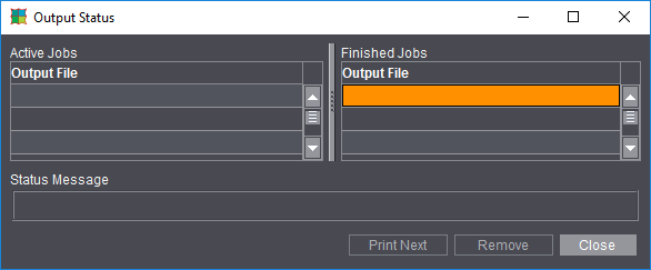
More details about output of the job can be found in the Output chapter.
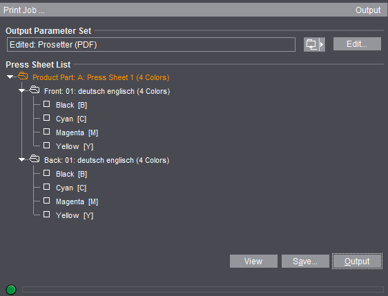
•"Output Parameter Set": Click the folder button beside this box to load an output parameter set from the resources.
Generally, this box has a default output parameter set (see the Default for the Output Parameter Sets).

Note: If you want your output to be centered, make sure that the imaging window is centered with regard to the plate template (see also Reference manual, Plate Template Editor).
•"Edit": This opens the Output Parameter Set Editor. You can modify the output parameter set specifically for this job in this editor. The modified output parameter set is saved together with the job if your job was output successfully. It displays as the default for the next job you output (see Default for the Output Parameter Sets).
•"Press Sheet List": You can select single press sheets for output. Output of all the press sheets is set by default.
You can also print the following parts of the press sheet separately:
·Surface (Front and Back)
·Separations (see the "View" item for details about displaying separated documents and composite documents on the screen)
•"Layer List": You also have a layer list when working with layers. You can select single layers for output. Output of the first layer is set by default.
•"Tile List": You also have a tile list when working with tiling. You can select single tiles for output. Output of all the tiles is set by default.
•"Select All": All the tiles in the list are selected when you click this button.
•"Deselect All": All the tiles in the list are deselected when you click this button.
•"View": Click this button to view your job as a PDF file on the screen.
You must have set the correct paths to the Adobe applications in "File > Preferences > Paths > Select External Executables" (see the Reference manual).
In the print preview, you must make a difference between composite documents and separated documents:
·Composite documents: In this case, Signa Station displays the imposed PDF press sheet in color. The single separations of the composite press sheet cannot be shown because Signa Station cannot create separations.
·Separated documents: In this case, the single separations of the press sheet are shown along with any comments in the Adobe message line. This means that the print preview shows exactly the data that will be sent to the RIP for printing. A color composite display of the separated page is not shown in this view. You can see a composite display of the separated pages in the graphic window.

Note: In some cases (e.g. if not all the colors on a surface are to be output) an empty preview displays.
Remedy: In Acrobat Reader as of version 8, you must change the default in "Edit > Preferences > Page Display > Overprint Preview" from "Only for PDF/X Files" to "Always" or "Automatic".

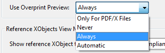
•"Save...": Like with "Print", you can output your job with "Save...". The "Save" dialog provides you with more settings:
·"Save to": This box lets you set a different output folder to the one defined in the output parameter set. The input is not saved.
·"File Name": You can edit the name of the output file in this box.
•"Output": The current job is output to the output folder. You already defined the output folder in the output parameter set > "General" tab.
You will find the "Output" folder that is created automatically for the output folder in "Preferences > Paths > Output".
•The progress bar at the bottom of the dialog indicates the period of time Signa Station will be busy with output and therefore will be locked for further work steps. In some cases (e.g. JDF with report), this process can take some time while the Signa Station can be operable again in other cases although output continues in the background.
Default for the Output Parameter Sets
There are three different sources for the default. The order in which the sources are used corresponds to the details given below:
•Job-specific output parameter set (internal resource, top priority): Normally, you have an output parameter set from the resources for the output of your job. You can modify this output parameter set using "Edit" in the Print Job dialog (see "Edit" in the Print Job dialog ). This modified output parameter set is used only in conjunction with the current job.
·The current output parameter set (it doesn't matter whether it's modified or not) is saved together with the job. This output parameter set appears as the default when you display the Print Job dialog again with this job.
•Plate template (second priority): You can define an output parameter set in the plate template. The output parameter set from the plate template is used as the default if you don't have a job-specific one.
In a product part, you can define several plate templates with output parameter sets. The output parameter set assigned to the first press sheet in the press sheet list is the default one. The output parameter set of the next press sheet is used if the first press sheet was not assigned a set, and so on.
•Last output parameter set selected (third priority): Signa Station always remembers the last output parameter set used that comes from the resources (i.e. not job-specific output parameter sets!).
This output parameter set always appears as the default if you neither have a job-specific one nor is there one defined in the plate template.
The situation the first time is an exception. You started Signa Station for the first time and want to output a job for the first time. In this case, there is no job-specific output parameter set nor is there one that was last used. You then have two options:
•You defined an output parameter set in the plate template. This is then set as the default.
•You did not define an output parameter set in the plate template. There is no default.
Print job from the Browser window
You can print a job or parts of a job from the Browser window.
Click the arrow button and select:
•For an entire job: "Print Job".
The product part names are used in the names of the output file if there are several product parts.
Click a product part and display the context menu:
•Product part: "Print All Press Sheets of the Product Part...".
Click a press sheet and display the context menu:
•Press Sheets: "Print Press Sheet".
Print job with the Print Assistant
The Print Assistant was implemented primarily for printing parts of very complex jobs. You can print front and back sheets, versions, layers, tiles and PDF-VT files as required.
You can set up print job s for different presses. This makes it very easy to print, for example, a cover on a SM52 and the body on a XL 106 in one print run.
The Print Assistant is structured in a logical order and you are guided through all your possible output settings.
The Print tabs that display are context-sensitive. They are shown or hidden depending on the content of the job. You can also deselect single tabs. The following tabs are possible in the Assistant:
The Print Assistant starts with the "Press Sheets" tab.
In this tab, you can select the press sheets you want to print with the mouse button or entering them in the text box. You can then print the selection you make here.
If required, you can hide tabs in the tab bar with "Active Stations".
Click the right arrow button to go to the next tab.
You can view the current version by clicking the "View" button in all the tabs.
PDF-VT: When printing a PDF file with variable data, you can enter in "Records" which data sets will be printed and how many. In "Partitioning", you can set how many files will be used for printing (example: Records: 1-1000, Partitioning: 100, result: 10 files, each with 100 data sets (pages)).
This lets you exclude front or back sheets from the output by deselecting them.
Select the press sheets with the mouse button and enable or disable the sheets you want ("yellow" is for front and "green" is for back).
This is possible with a mouse click or with the "On" and "Off" buttons on the left.
Color can be ignored in the output.
You can select/deselect layers for output in jobs with several layers (e.g. language-dependent jobs).
You can select/deselect tiles for output in jobs where tiling is enabled (e.g. large-format jobs).
The "Parameters" tab is only active if you enabled "Output Parameter Set Automatic" in "File > Preferences > Defaults".
You can assign different output parameter sets to the single press sheets. You can also edit the output parameter sets.
The imagesetter planned for output displays for each sheet (in the table below "Parameters").
You can change the press by assigning a different output parameter set to the sheet.
You can edit assigned output parameters.

Note: The setting "All in one job" in "Options" in the output parameter set is ignored in this case.
You define the workflow in the output parameter set in the "General" tab > "Workflow > Device and Variant". You select the workflow in the list box in "Device". Then only the outputs possible in combination with the device are shown in the list box in "Variant".
The workflows that are available in the list box will be explained in: Workflows.
Proofing with Adobe Reader
Signa Station treats the proofer (color printer, plotter, etc.) like a third-party RIP. At present, you cannot output a PDF file directly from Signa Station to a proofer. For that reason, we are proofing a PDF file from Adobe Reader.
1.You can launch Adobe Reader in two ways:
•You click "View" in the Print Job dialog.
•You go to your output folder and right-click the PDF file you want to output. Select "Open with Adobe Reader" in the context menu.
2.In Adobe Reader, select "File > Print" or click the Printer icon.
3.Select your proofer in the "Printer" group.
4.Start printing.

Note: In some cases (e.g. if not all the colors on a surface are to be output) an empty preview displays.
Remedy:
In Acrobat Reader as of version 8, you must change the default in "Edit > Preferences > Page Display > Overprint Preview" from "Only for PDF/X Files" to "Always" or "Automatic".
Acrobat setting for "Overprint Preview":

You can also set up your proofing internally at the RIP (even a third-party RIP).