Inspectors in the 'Packaging' Mode
In the "Packaging" mode, the "Attributes" tab in the Cutting Die Inspector displays the following functions:
•Current Assembly Block
The block name of the imported cutting die file displays. You can modify this name manually here.
•Cutting Die Parameters (Packaging)
Same Content for All 1ups
When this option is set, all the 1ups of an assembly block are assigned the same content. In the graphic window, you will see that all the 1ups of an assembly block have the same number.
The same function is also available in the Press Sheet Inspector.
"Position X" / "Position Y":
This allows you to enter the position of the selected assembly block (yellow contour) relative to the press sheet. The bottom left corner of the paper is the zero point for both directions.
The same function is also available in the Press Sheet Inspector. Using the parameters "Position x/y", you can change the position of the selected assembly block relative to the press sheet in this tab as well.
"Left Margin / Right / Top / Bottom"
This can be used to define additional space at the respective margin of the cutting die. For newly created jobs, the margin values from the Preferences defined in the "Packaging" tab under "Cutting Die Margin" are entered by default.
•Lenticular Printing Settings
See Lenticular Printing Settings .
In the "Packaging" mode, the "Attributes" tab in the 1up Inspector also displays a "Clip Path" group with the following functions:
•"Set Original": When this option is set, the original clip path from the cutting die file is set for all the selected 1ups.
•"Copy": The clip path of the selected 1up is copied.
•"Paste": A copy of the clip path is pasted for the selected 1ups.
•"Move Corners to Contour": This function is useful if a clip path is a bounding box around the 1up. When this option is set, the four corners of the clip path move in closer to the hull of the cutting die of the 1up. In "Distance", you can define a minimum distance from the cutting die for these corners. The trim from "1up Inspector > Trim > Left/Right/Bottom/Top" is also taken into account in this value (see the Rectangular Clip Path ).
You can define a rectangular clip path in "1up Inspector > Bleed > Left/Right/Bottom/Top".
A clip path may already be defined in the cutting die file. You can view this clip path in the graphic window. In this case, the line type of the clip path in the cutting die file must be identical to the line type you defined in the "Packaging" step in "Line Type for Clip Path".
The bounding box of the 1up is used by default as the clip path if a clip path is not defined in the CFF2 file.
Requirements for editing the clip path:
•You have a job in the "Packaging" work mode or a Montage job.
•The "Folding Sheet/Assembly Block/Cutting Die" tab is selected in the graphic window.
•You have selected a 1up.
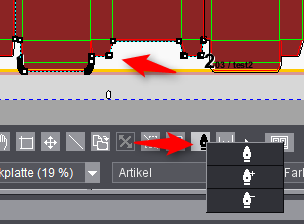
The lines of the selected 1up have different colors:
clip path = cyan-and-black dashes, cutting die = magenta
The corners of the clip path are highlighted by squares when you go to the edit mode.

Caution: Your changes are lost if you start the Signa Station Packaging Pro or Label Pro option after having edited clip paths! For that reason, we recommend that you rework clip paths for packaging jobs from the start in Signa Station Packaging Pro or Label Pro and not directly in the layout in Signa Station.
The following tool is available for editing the clip path:

You will see this "pen nib" button in the button bar below the graphic in the graphic window > "Folding Sheet/Assembly Block/Cutting Die" tab.
The pen nib button is enabled with the left mouse button. In this case, the mouse pointer also appears as a pen nib in the graphic window.
You can edit the clip path with the pen nib cursor. The pen nib cursor has three modes. You can select them in the context menu of the pen nib button. To do this, right-click the enabled pen nib button or use the shortcuts described below. You can see which cursor mode is set from the pen nib button.
The functions of the three modes will now be described:

Click a clip path line with the left mouse button. This selects the vertices (corner points) of this line. One of the two vertices is marked by a "cross" (fixed point), the other has a red frame. When you insert a new vertex between the selected vertices, the line changes course accordingly to include the "new" vertex you inserted (insert mode).
You can also select a single vertex by clicking it and move it holding down the mouse button. The selected vertices are moved.
Press the Shift key if you wish to select several vertices. The cursor doesn't change when you do this. Click one of the selected vertices with the left mouse button. You can move the entire selected line holding down the mouse button.
Remember: You return to the bounding box of the 1up after all the polygonal paths are deleted, and the tool is in the Insert mode.
You can change the pen nib mode or edit the clip paths with the following shortcuts:
•"Ctrl + click on line": Adds a point.
•"Ctrl + Alt + click on a point": Deletes the point.
•Shift + click on a point: Selects or deselects points.
•"Ctrl + A": Only in the graphic window, selects all points.
•Left mouse button + draw box: Only in the graphic window, selects several points.
•"Ctrl + X": Only in the graphic window, deletes all selected points.
Pen nib button with plus sign:

The pen nib cursor has a plus sign when it is near the clip path.
Click a clip path line with this cursor to set a new corner. You can now move this corner holding down the mouse button.

Note: You can also give the pen nib cursor a plus sign by a shortcut. To do this, press the Ctrl key (PC) or the Apple key (Macintosh) on your keyboard.
Pen nib button with minus sign:

The pen nib cursor has a minus sign when it is near the clip path.
You can delete a corner by clicking it with this cursor. The clip path line is drawn between the two remaining corners.
Functions in the context menu of a 1up
Requirements for displaying the context menu are:
•You have a job in the "Packaging" work mode.
•The "Folding Sheet/Assembly Block/Cutting Die" tab is selected in the graphic window.
•You have selected a 1up.
Right-click the selected 1up to display the context menu:
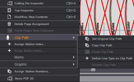
Functions:
•"Clip Path": The first three functions ("Set Original Clip Path", "Copy Clip Path" and "Paste Clip Path") are also available in the 1up Inspector. A description of the functions can be found in the 1up Inspector.
•"Clip Path > Define Line Type as Clip Path": The mouse cursor changes to a crosshair when you select this function. You can click any line of the cutting die with this crosshair. This path is defined as the clip path if this line forms a closed path with other lines of the same type.
This function saves you having to know and enter the line type as the clip path (see the Cutting Die File and Main Settings).
•"Change Station Index and Article": Select one or more 1ups and then click the "Change Station Index and Article" function.
A window displays where you can change the station index or article using list boxes and editable boxes.
You can find a description of other functions relating to the clip path in the 1up Inspector.