The measured data are shown in the "Press Sheet", "Folding Sheet/Assembly Block/Cutting Die" and "Document" tabs.
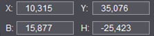
The "X", "Y" coordinates show the current mouse cursor position. You can set a measuring position or create a frame with the shortcut "command key + Shift key" while holding down the mouse button. The values in "W" and "H" refer to the width and height of the frame.
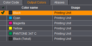
The color channel is shown in the "Press Sheet", "Folding Sheet/Assembly Block/Cutting Die" and "Document" tabs.
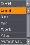
The "Channel" list box shows you which colors are used on the active press sheet, folding sheet/assembly block/cutting die or single page.
You must have an imported, separated PDF file for the multi-channel display to work.
To check single separations and any spot colors, select the separation/spot color you want to check in the list box. The selected color is displayed.
All colors are displayed when you select "colored" (composite view).
Default setting: colored
The zoom is shown in the "Press Sheet", "Folding Sheet/Assembly Block/Cutting Die", "Press Sheet List" and "Document" tabs.
The main functionality is found in the "Press Sheet" tab. The focus of the zoom can be the press sheet or paper, depending on what is selected.
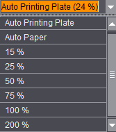
The "Zoom" list box shows you the zoom factor in which the press sheet, the press sheet list, the folding sheet/assembly block/cutting die or the single pages/1ups will be displayed.
To change the zoom factor, select the one you want from the list box or mark the box and type in a value.
"Auto" automatically calculates and shows the largest possible full size of the press sheet or folding sheet/assembly block in the window.
Default: Auto(matic)

|
To select an object. Click an object that can be selected. This object then has a yellow frame and you can move it holding down the mouse button. You can select several objects at a time by drawing a box around them; this applies to objects of the same type only. The type of objects to be selected depends on the object that was clicked when drawing the box. Another way of selecting multiple objects is to keep the Ctrl key pressed while clicking additional objects. |

|
To select solely folding sheets or assembly blocks. Click an object that can be selected. This object then has a yellow frame and you can move it at once holding down the mouse button. You can select several objects at a time by drawing a box around them. Another way of selecting multiple objects is to keep the Ctrl key pressed while clicking additional objects. |

|
To zoom up the entire graphic. A "+" appears in the magnifying glass. Hold down the "Alt" key to zoom down. A "-" appears in the magnifying glass. You can scale up a certain part of your work by drawing a bounding box. |

|
Hand tool: Lets you move scaled-up objects into the view frame. Click and move the mouse to do so. You can also select the tool by holding down the space bar and clicking the mouse. |

|
To set a measuring point and create a frame: This tool lets you set measuring points or create a frame and read off the values in the read-only boxes on the bottom left. You can now also create internal marks the size of the frame you created. See Creating Internal Marks. |

|
Swap the contents of the 1ups using drag-and-drop Click the button: The mouse pointer changes accordingly. The contents and indices of two 1ups are swapped when you click one 1up and drag it to another one. The hull must match and the indices of the two 1ups must be different. The function behaves differently in each of the work modes: Packaging In the "Packaging" mode, the page indices and the contents of the 1ups are swapped. In this case, the contours and the indices of both 1ups must differ. Assembly There are two scenarios in the "Assembly" mode: 1. An assembly block has several 1ups: in this case, the pages are swapped like in the "Packaging" mode The sizes of the assembly blocks must be the same, and the 1up indices different. 2. There is one assembly block for each data page. This is the case with multiple sheet optimization. Here, drag & drop will not swap the pages but the entire assembly blocks. The sizes of the assembly blocks must be the same, and the 1up indices different. Web to Print After optimization in the gang run job, you can use the swap tool to swap folding sheets of exactly the same size. They must contain different folding sheet pages. Imposition In the "Imposition" mode, you can swap folding sheets of exactly the same size. |

|
You can scale all marks except for the automatically placed cut and fold marks. As an alternative to the tool: "F5" Select the mark you wish to scale and hold down "F5". The handles that appear let you scale the mark invariably. Enable the tool if you wish to scale proportionally. First enable a handle with the mouse pointer and hold down the mouse button. Then press the Shift key and move it using the mouse. |

|
This tool lets you measure from one defined edge (e.g. paper edge, page edge, etc.) to another defined edge. •Move the mouse pointer to the page edge. •The starting edge is shown as a red bar. •Hold down the mouse button and drag the mouse pointer to the paper edge. •The target edge is shown as a green bar. •Let go of the mouse button. •The distance from the page edge to the paper edge is shown along a line between the red and green bar. •Use the shortcut "Alt + click" to delete the dimensions. |

The "white" button lets you view the front and back sheets side by side. The "green" and "yellow" buttons let you view the front or back sheet respectively.
You can trigger the same function as the "white" button with a double click on the colored caption bar of the front or back sheet. See Mouse and Keyboard Shortcuts in Graphic Window .
Toggle true-color overprint preview of press sheet on/off
On:

Off:

This button offers a true-color view of the press sheet. This view also shows correctly for each color how pages and marks elements overlie on the press sheet.
You can zoom and pan in the print preview. You can neither operate the context menu nor any of the tools.

Note: Zooming and panning of contents files with large data volumes can take longer because the preview is recalculated each time.
Automatic Function for Automatic Cut and Fold Marks

The button makes it possible for you to edit cut and fold marks that are normally locked. This can be necessary in special workflows.
Automatically placed cut and fold marks cannot be changed to start with because the positions of these marks are always unique. These elements are indicated by a red frame in the graphic window when you select them. You can modify the marks only by explicitly unlocking them in the graphic window. The marks then are highlighted by a yellow frame.
Use this button to enable and disable the automatic feature of the marks. Click the button when in the automatic status; a prompt displays with a brief explanation. When you confirm the prompt positively, the button and the affected marks turn yellow and can be modified. As of this point in time, there is no automatic feature, for example, to set new mark positions. Custom changes are now possible.
|
Automatic |
Button |
Marks |
Edit marks |
Consequence |
|---|---|---|---|---|
|
ON |
colorless |
Marks have a red |
Not |
Automatic corrected if necessary |
|
OFF |
yellow background |
Marks have a yellow border |
is |
Automatic is disabled, the product part is locked |
|
ON to OFF |
changes from colorless to yellow background |
Marks get a yellow border |
is |
Automatic will be disabled, the product part will be locked |
|
OFF to ON |
changes from yellow background to colorless |
Marks get a red border |
is |
Automatic is enabled again and overwrites manual changes to marks |
Explanation:
Automatic feature will be disabled (OFF: yellow background)
Marks that were removed automatically beforehand, for example, by moving folding sheets and resulting overlaps are not redrawn. No new marks are set automatically.
Locking of the product part is enabled (if enabled in the Preferences). This disables functions that would set off the automatic feature.
Additional note
The button state "OFF" or "ON" is an attribute of the job. The job is saved and opened accordingly.

Click this tool to show or hide the values of the "User-defined dimensions" tool (see above). All the parameters enabled in "View Properties > Dimensions" are also shown. See View Properties and Enable/Disable Layers .
View Properties and Enable/Disable Layers

Click the "View Properties" button to display a dialog where you can configure the way the graphic window will appear on your screen.
The "View", "Dimensions" "Grid", "Snap Lines", "Dielines " and "Separations" tabs are available for the configuration of the graphic window.
The "Save as Default" button at the lower part of the window lets you save a modified setting immediately in the Preferences. This setting is effective even after the program is exited.

Note: When you work with several languages, the active layer is displayed in the "View" tab.
Select the layer you want if several layers can be shown. The active layer is shown directly in the graphic window. Several or even all the layers can be shown.
Files are imported to different layers in the Browser window > "Contents".
You can customize the graphic window with the parameters below. Basically, the parameters available in the job display in the graphic window as well.
View
•Contents of Page/1up
The page content appears as a preview.
You can cut down computing time if the contents are hidden in documents with a large number of pages.
•Segments

Note: Only when "Gang & Sheet Optimizer" is enabled and with the additional option "Ganging with Segments for Finishing".
For "Ganging Optimization without Layout Default" jobs, sections can be formed on the press sheet that, depending on the product code, group articles with the same finishing on the sheet.
When the "Segments" view is enabled, these areas display with a border matching the color defaults from the segment templates.
In the example shown, the left article is part of a segment (blue border), the right article is not part of a segment (no border).
•Symbols
You can hide all symbols that are not relevant for output.
•Imaging Window
The blue-and-white line is shown or hidden.
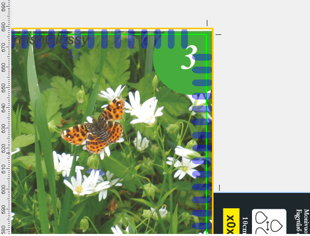
•Show Order Number of Folding Sheets
Numbers the folding sheets consecutively and marks them with the appropriate number. The order corresponds to the index of the "Folding Sheet List" in the Press Sheet Inspector.
During imposition, you can also use the order number with the "StationNumber" mark. This lets you tell the folding sheets apart if there are 1up copies. See Usage in the 'Imposition' Mode to keep folding sheets distinct for details.
•Tiling Numbers
•Replace Placeholder by Placeholder Name
The name of the placeholder is inserted if no content can be replaced in the placeholder of a mark. In this way, the mark can be seen.
•Background Marks
•Foreground Marks
•Flexo Marks
•Ruler
•Ink zones
The ink zones defined for a press are shown as lines. The press selected in the plate template is taken as the basis for this. The values for "Number" and "Width" in "Ink Zones" in the Press Editor are used.
This functionality facilitates the positioning of color control bars, for example.
•Show Back Folding Sheet as in Press Sheet
The folding sheet view shows the same orientation for the folding sheets as the press sheet view.
•Show Proof Lines
Shows the proof lines defined in the output parameter set.
Shows details about the template of the selected press like positions of the gripper or suction cups.

Prerequisite: The press must have been defined in the "Plates" step in the list of plate templates.
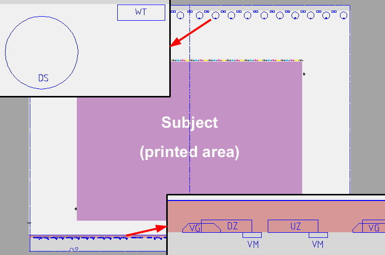
The scale and position of all the grippers, etc. belonging to the press display. You can change the color of the view in the "Preferences" in the "General" tab (see Display color). The following abbreviations are used:
"DZ" for print cylinder gripper
"UZ" for transfer cylinder gripper
"VG" for transfer gripper
"VM" for front lays
"WT" for perfecting drum gripper
"DS" for rotary suckers, storage drum
At present, this functionality is available for the following machines:
·CD74
·CS92
·SM52
·SM74
·SM102
·XL75F
·XL75C
·XL106
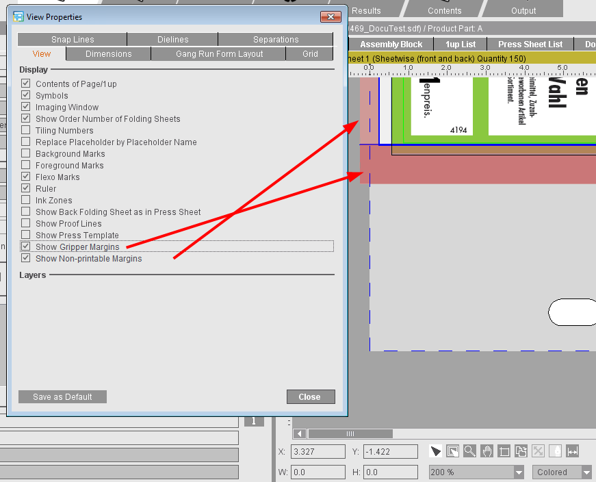
•Show Gripper Margins
The gripper margins are shown by default. If gripper margins and non-printable margins overlap, these areas are indicated by a darker red.
•Show Non-printable Margins
The values refer to the paper. This means that the areas of the paper that cannot be printed by the selected machine are marked red. The values are taken from the machine parameters. These are hidden by default.
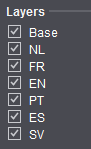
•Layers
A job with several layers (e.g. language versions) displays them; you can disable single ones if required.
Default: All the parameters with the exception of the last four and the order number are shown.
The size data shown can also be displayed in different colors and font sizes. To do this, you can change the color or font to the one you want by clicking the color button or the box with the font size.
The graphic window can show the following size data:
•Press Sheet
•Paper Position
•Paper Size
•Subject Position
•Subject Size
•Folding Sheet/Assembly Block Positions
•Folding Sheet/Assembly Block Size
•Page/1up Positions
·Positioning across folding sheets
•Page/1up Size
•User-defined
Shows any values measured with the User-defined dimensions: function.
·Show Small Values
Also shows very small measured data.
·You can edit the colors of the dimensioning lines and the measured data separately. Likewise you can edit the font size of the measured data displayed.
Default: Dimensions are hidden.
You can edit the view of the graphic window by clicking "Gang Run Form Layout". Information and the arrangement of placed 1ups are shown.
The function also shows the set placeholders (layout) in a normal job, where "Gang run form" is not enabled.
To view the contents of the pages/1ups, disable the option again.
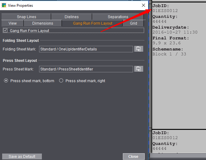
•"Gang Run Form Layout"
Enables the view of a gang run form layout.
•Selecting Marks
You can select different marks for the folding sheet and press sheet layout. The default mark for the gang run job layout of the folding sheet is the "OneUpIdentifierDetails" mark, and for the press sheet the "PressSheetIdentifier" mark in the "Standard" group. These marks are selected automatically unless other marks were set.
•Position of the press sheet mark
By default, the position of the mark is set to "bottom" on the press sheet. If desired, you can position it at the "right" beside the press sheet and can change its width and orientation. This may be a good idea when printing a gang run form layout.
You can then also set the width using the measuring frame. The button to the right beside the text box applies the values. The selected mark is then scaled to the rubberband (set width and press sheet height) and centered in it.
You can save a setup as a default for new jobs.
•Marks used for the gang run form layout have the following properties:
·the marks are in the foreground, and the background of the marks is covering
·the marks are not shown in the Marks Inspectors and not printed either
·the marks are automatically scaled to the size of the 1up and shown in black
·the marks are visible only if this is enabled in the "View Properties"
The gang run job layout is related to the folding sheet. This means that for packaging jobs the gang run form layout covers the entire cutting die. But in this case, a 1up-related gang run job layout is desired to display information such as article, article number, etc. for each 1up. To obtain a packaging-compliant gang run from layout, you can use the standard mark "OneUpIdentifierPackagingDetails" in the "Standard" group.
As packaging blanks usually are not rectangular, the gang run from layout is placed on the remaining area when 1ups overlap. This is why 1ups of identical contents can appear to have different sizes in the gang run form layout.
You can show a grid in the graphic window:
You can set the size (in the selected unit of measure) and the color of the grid.
The grid is not magnetic and is only a visual aid.
Default: Grid is hidden.
You can set vertical and horizontal snap lines.
You create a line by clicking the "New" button and you can then position it with the mouse pointer or by entering values for the position.
Relative to Ruler
When this option is set, the snap lines move with the ruler when you shift the zero point; otherwise they remain at the position set.
Show Main Profile
Show all lines
Show Line Width Original
Show the original line width.
Station Index Centered
The station index displays at the center of the 1up.
The separations implemented in the job are shown.
You can show or hide these separations by clicking the appropriate ones.
Previews with Transparency
When this option is enabled, transparency elements are also written to the data and displayed.
The "Frame" tool (display with the shortcut "command key + Shift key") lets you create all Prinect Signa Station mark types as internal marks. The bounding box defines the position and size of the mark.
You can use the following marks tools in the graphic window to create "internal marks". These internal marks are not filed in the marks resources and are only available in the current job.
You will find the marks that are assigned to the job in the "Browser window > Internal Resources" or in the relevant inspectors in the "Marks" tab.
To add an "internal mark" to the global resources, go to the "Browser window > Internal Resources", select the mark and display the context-sensitive menu. Select "Copy Internal Mark to Clipboard" and paste the mark in "Marks Resources" in an inspector with "Paste Mark".

This tool allows you to display the Marks Editor the size of a rectangle you created beforehand and to create and position a mark. See the Marks Editor to learn how this function works.

This tool allows you to create and position a text mark the size of a rectangle you created beforehand.
•Using the measure tool, draw a rectangle whose size and position are that of the text mark you want. (To do this, press the command and Shift keys and create the rectangle holding down the left mouse button. Release the mouse button first).
•When the rectangle is created, a toolbar appears at the bottom of the graphic window.
•Click the text mark button.
•The Text Mark Editor opens, displaying a text mark the size of the rectangle you created. See Creating a Text Mark for details on what to do next.

This tool allows you to create and position an ink pickup bar the size of a rectangle you created beforehand. See the Ink Pickup Bar with Measure Tool to learn how this function works.
Ink pickup bar on output colors
The ink pickup bar can now be set directly on output colors.
In the Ink Pickup Bar Editor, you can set output colors in "Choose Color Layer". The color you select here is different to the color code that is assigned. This makes sure that the color you select is assigned correctly.
Creating a cover mark and other internal marks

This tool button allows you to create a cover mark, a cutting die mark, a line type mark for the glue area. a color control bar or a special color control bar. You can also import a mark that you can then create and position and whose size is defined by the frame you created beforehand.
•Using the measure tool, draw a rectangle whose size and position are that of the mark you want. (To do this, press the command and Shift keys and create the rectangle holding down the left mouse button. Release the mouse button first).
•When the rectangle is created, you are now able to use the above tool button at the bottom of the graphic window.
•Select the tool you need.
•If you are creating cover marks, see Cover Marks (Job-internal Cover Mark / 'CoverClippath'), Create Cover Mark from CAD Lines and Define cover mark from line type for glue area. In the other cases, the Marks Editor , Color Control Bar Editor , Color Control Bar Special Editor or the Marks Import Editor displays, depending on what you selected, where you can then edit your mark. The mark displays in the size you created the rectangle.