Use this editor if you wish to create/edit a new set of output parameters that is saved as a resource in "Output Parameter Sets".
• "Name": Displays the group folder name and the name of the output parameter set that you can edit.
•"Output Device": You can choose between an imagesetter and a digital press.
•"Imagesetter data set": This is where you select a filmsetter or platesetter in "Filmsetters" or "Platesetters" in the Browser window. To do this, click the folder button on the right. All installed filmsetters or platesetters will then be shown.
The name in the "Data set" box comprises
a) the group folder name of the imagesetter resource and
b) the name of the imagesetter.
•Digital press data set: Select the relevant machine resource.
•"Material": (imagesetters only) You cannot edit the material but only select it from the list box. The "Width" and "Height" show the size of the imaging window.
"Width": Slow scan direction
"Height": Fast scan direction
You can only change the imaging window/max. paper size of the materials in "Machines" in "Resources & Machines".
You select the workflow in the list box in "Device". Then only the outputs possible in combination with the device are shown in the list box in "Variant".
Possible combinations:
|
|
Output (Variant) |
|
||
|---|---|---|---|---|
|
|
|
JobTicket |
JDF |
Prinect |
|
Device (Workflow) |
|
- |
|
|
|
Prinect |
- |
- |
X |
X |
|
Prinergy |
- |
X |
X (=>4.1) |
- |
|
NexPress |
- |
X |
- |
- |
|
Other device |
X |
- |
X |
- |
For the "Prinect Renderer (via JDF)" variant, you must also enter the output type. This is where you specify the code of an output parameter template that controls the type of output in the Prinect Renderer (comparable with the previous "Output Plan" in MetaDimension). You can find more details in: Workflow: Prinect Renderer (via JDF)
•"Output folder for PDF, JDF, JT": Click the folder button to the right and select the output folder for your output data in the Browser window.
•Settings for "Prinect Business Manager": Displays if option set up. Click the folder button to the right and select the folder for transfer of the layout.
The basic name for printing is set by default if this option is enabled in the output parameter set.
For example, you can assign each press its own naming scheme:
If you are printing with output parameter set "XL162", the name in the text box could be "Heidelberg XL162". In addition, you could add placeholder "Job Number" to the end of the name.
•"All in one job": All the press sheets are output in one job.
·Advantage: High processing speed.
·Disadvantage: If the output in large complex jobs is faulty, the entire job must be output again after the error is eliminated.
•"One job per press sheet or web": One job per front and back printing or per web is output.
·Advantage: If the output in large complex jobs is faulty, only a part of the job must be output again after the error is eliminated. This saves you time and material.
•"One job per surface": A job is created for every front and every back.
·Advantage: If the output in large complex jobs is faulty, only a small part of the job must be output again after the error is eliminated. This saves you time and material.
·Disadvantage: The capacity of your output device is not always used optimally.
•"Print press sheets in reverse order": Output starts with the last press sheet.
•"Rearrange Back": For the back, you can switch from "Sheetwise" to "Perfector" or vice versa as the placement rule. This option lets you change your output fast and simply without having to modify the job settings.
This setting is used for finishing.
•"Automatic": The press sheets are rotated automatically by 90° if they do not fit the output material.
•"Portrait": The sheets are output in portrait format.
•"Landscape": The sheets are output in landscape format.
•"Mirror horizontal" / "Mirror vertical": You can mirror the sheet horizontally and/or vertically.
Conversion of spot colors to CMYK
•"Convert Spot Colors to CMYK": Spot colors in a job are not printed as they are but are converted to CMYK and printed with the corresponding CMYK values.
You cannot use this function in the PDF workflow with separated data.
The Renderer workflow (device="Prinect", type="Prinect Renderer") is a special case in this: In addition to the options of no conversion or converting all the spot colors in the Signa Station output to CMYK, it is possible to handle spot colors of the job through settings defined in the Prinect workflow.
You can scale the sheet up or down in percent (minimum=10%, maximum=500%) in x direction (horizontal) and y direction (vertical) for your output. The X and Y values must be the same in tiled sheets.
These parameter sets allow you to set RIP parameters such as screening or resolution.
Imagesetter Imaging Window
The imaging window you have for output results from the imaging window of the plate template.
Paper
The imaging window you have for output results from the paper dimensions.
Tiling
Tiled sheets will be output. The imaging window results from the number of tiling marks on the paper. See also Tiling and Paper Output.
Alternative Plate Template
You can select a different plate template for output. The imaging window of the alternative plate template is used, and all the marks of the original plate template are replaced by those of the alternative plate template. The changes only affect output and not the job itself. This makes it easy for you to change the target device you want for output. The imaging window you have for output results from the imaging window of the new plate template you selected.
Is enabled if "Paper" or "Tiling" was selected in section "Imaging Size".
•"Don't generate tiling marks": You can select to output your tiled sheets without any
tiling marks.
These are eight registration marks and a text mark that identifies the tile. All these marks are placed automatically in the "Extra space" (see below).
•"Extra space": Extra space defines the width of the margin that fully surrounds each tile. This margin is required for the tiling marks that are set automatically ("TilingRegister" and "TilingText" marks).
You increase the tile size by defining extra space. You must make sure that the maximum output format for the imagesetter is not exceeded when you do this.
In the "Horizontal" and "Vertical" boxes, you can enter the values by which the press sheet for the back will be moved in relation to the center. For example, this lets you offset tolerances in machines that print front and back at the same time. You can check the result in the "Print Job..." dialog in the "View" function.
Table with defined proof names
Displays the predefined proof names.
Use One Proof Color
Only the selected color is used for all areas during proofing.
If the option is disabled, you can select different colors for each area in the table.
Print Proof Marks with Less Ink
You can output marks with less ink during ImpositionProof.
You can enter a reduced value in percent in the Marks Editor in "Ink Coverage in Proof".
Print Dimensions Like in Graphics
The dimensions currently enabled in the graphic window are also output as Proof Color during ImpositionProof.
This requires that the "Use One Proof Color" option is also enabled.
•"Mode": This is where you can select whether the punch settings will apply to the entire press sheet or only to single tiles of the sheet.
You can edit this section if you opted for the "Tiling" mode.
•In the list box, select the tile that is to have punch settings.
•"Rotated": The selected tile is output rotated by 180° if "Rotated" is enabled. Rotation causes the tile to be punched on the opposite side.
Make sure that you rotate the correct parts if your output is mirrored.
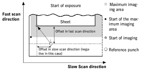
The data in this group defines the imaging starting point within the max. imaging area.
You must make sure that the tiles of a sheet do not lie outside the maximum imaging area.
•"Reference punch": The reference punch is used as a reference point for defining the imaging starting point. The center of the punch hole is the zero point for calculating the imaging start.
Select the punch in the list box that will be the reference punch. The reference punch selected is shown in the graphic with a frame around it.
•"Fast Scan Offset", "Slow Scan Offset": The offset values in fast scan and slow scan direction are the distance between the reference punch and the imaging start.
The center of the reference punch hole is the zero point for calculating the imaging start. Offset values counter to scan direction are negative, offset values in scan direction are positive.
The reference point on the sheet is the lower left corner of the sheet (for a non-centered output). This means that the sheet is positioned with the lower left corner on the calculated imaging start.
Calculation of the imaging start with a non-centered output
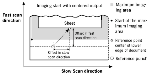
•"Centered output": During output, the sheet is centered to the reference point if this option is enabled.
In this case as well, offset values affect fast scan and slow scan direction. In a centered output, the reference point on the sheet is the middle of the sheet edge concerned.
Calculation of the imaging start with a centered output
You can generate additional PPF files.
These files only contain PPF files that were generated by the Signa Station. This can be helpful if you only need cutting data, for example, and not any data about ink zone control. In this case, the PPF file is much smaller.
There is the "Cip" folder that is created automatically for these PPF files.
The PPF files are generated as follows, depending on your output mode:
See "Output Parameter Set Editor > Options > Output":
•"All in one job" and "One job per press sheet or web":
A PPF file will be generated per press sheet or per web.
•"One job per surface":
A PPF file will be generated per surface.
Select the shape and number of staples for saddlestitching in these two list boxes.
Shape and number of staples
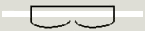
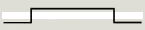
Overview of staple shapes:
|
Crown / Normal |
|
Overlap |
|
Butted / Normal |

|
ClinchOut |
|
Eyelet |
The system has to match certain job parameters for DataControl, PECOM and more recent MAN web presses in the background:
Not specified
All the parameter defaults are kept.
with DataControl
In this case, the sheet name must have a certain syntax that DataControl can interpret.
If you are working with DataControl, you must check this option so that the Signa Station automatically generates the sheet name with this syntax.
with PECOM
In this case, the job name must have a certain syntax for finishing that PECOM products can interpret.
If you are working with PECOM products, you must check this option so that the Signa Station automatically generates job names with this syntax.
In this case, the sheet name must have a certain syntax for finishing that more recent MAN web presses in particular can interpret.
It is crucial that this option is selected for more recent web presses with an IDI interface.
You can mask the "Klebrand Code Mark" for Inspection Control.
This functionality is applicable only for submission to the Prinect workflow.
Mask for Klebrand Code
The mark is masked in a suitable resolution.
When this option is set, an output report in the form of a table with all relevant output data is written as HTML or PDF to a set folder (path).
To generate preferences for the reports, see Reports .
The reports are used primarily in connection with a WST barcode reader.
Automatic XML- Reports for JDF Output
File reports in gang pool
The XML report is filed in the subfolder of the gang job. This requires that your job is a ganging optimization one that gathered the single job components from a gang pool. In this case, the processed job components are moved to a subfolder of "Work&Done". The matching XML report is filed to this.
Note: Independently of this, a fixed folder can now be defined in the Preferences where all XML reports are stored centrally.
Loading the 'Output Parameter Sets' Resource to the Job
This is where you load the "Output Parameter Sets" resource to the job:
•The print job dialog displays or you can use the "Output > Edit..." step for output of your job ("File > Print job"). You assign the output parameter set to your job in this dialog.
The output parameter set can be defined in the "Output Parameter Set" resource and you can load it through this resource:
•Plate Template Editor and select output parameter set resource
•"Output > Edit..." step