
Preferences / Getting Started
Preferences and Getting Started
This chapter will help you to configure Signa Station as you need it and to create your first job in the "Automatic Imposition" mode. To create jobs, you need resources that you can create later for your own device setup. For your first job, however, we will use the default resources. See Creating Custom Resources for details about creating your own resources.
In the Preferences, you can set parameters that simplify working with Signa Station.
You can save, close or reset your settings at any time in the dialog:
•Close
Click this button to discard any changes you made in all of the tabs and close the window.
•Reset
Click this button to reset your settings in all of the tabs back to the last version saved.
•Save
Click this button to save all the changes you made in all of the tabs.
Note: Even if "Use Global Settings..." is enabled in the Preferences in "General > Used Setting", some preferences still remain user-specific, i.e. they relate only to the user who is logged in. This includes, for example, computer-specific installation paths when selecting external executables, view attributes, language or license options in "Licensing" as the same licenses do not always have to be enabled on all the computers.

Note: It is possible to edit the Preferences only if a password was not assigned or if the correct password was entered when opening the Preferences.
In this tab, you configure the way Signa Station will display on your screen. In addition, a preview of PDF files can be displayed automatically when they are being loaded.
Use Global Settings (are filed in current workspace)
Preferences can be filed "centrally" like resources and used jointly by all users.
When this option is enabled, the structure set in "Preferences > Paths > Workspace" in Signa Station is applicable. A preferences file that is already in this workspace, for example, from a previously installed Signa Station will be used. A restart of Signa Station is necessary if different preferences are detected in order for the most recent one to be used.
If the workspace does not yet have any preferences, the local settings are copied to the workspace and are then applicable as global settings that other users can also access.
The preferences (if there are any) of the local user who is logged in are used if the option is disabled. A message describes the preferences that are then used.

Note: You must enable this option above all if you are working with the Prinect Signa Station Server and other connected Signa Station systems are to access the same settings and data. In this case, the "default folders" must also be set to the same network directories (usually on the server) in "Paths". You will find basic information about the Prinect Signa Station Server in the section Notes on the Prinect Signa Station Server Option.
Units in text boxes
The selected unit is shown in boxes where dimensions are specified.
You can change the name of the paper in the "Plates" step.
This function should not be enabled in the Prepress Manager workflow and with the MDS (Master Data Store).
This is a global setting that is not applied immediately to an open job. The function is applied only when you reopen the job.
Tooltips
A tooltip appears or is always hidden.
If you let the pointer hover over an element, e.g. a button, for a moment, a tooltip appears explaining what this element is for.
The unit selected in the list box is used as the default unit of measure for your work with the Signa Station application.
Existing values are immediately converted to the new unit if you change the unit of measure in the list box (e.g. from centimeter to inch).
The following units of measure with their equivalents in millimeters are available:
|
Unit of measure |
Conversion to millimeters |
|---|---|
|
1 millimeter |
1 mm |
|
1 inch |
25.4 mm |
|
1 centimeter |
10 mm |
|
1 meter |
1000 mm |
|
1 point |
0.353 mm |
|
1 Pica |
4.21 mm |
|
1 Cicero |
4.51 mm |
|
1 Didot |
0.376 mm |

Note: Numbers that have more than three zeros after "0." are shown as exponential numbers.
An example is given below:
After changing the unit of measure to meter, the value of 0.06 millimeter would have to be displayed as 0.000006 meter. However, since the boxes cannot show an infinite number of digits, the value in our example is shown as an exponential number, 6E-5 meter.
The first digit '6' describes the real value, the second digit '5' after the 'E' the number of zeros after the decimal point.
This is where you configure the background color for the
Graphic Functionality .
You can give the various areas different colors to be able to clearly tell them apart, e.g. the plate and paper you use. "Folding Sheet/Assembly Block", "Paper", "Plate", "Page without Content", "Page with Content", "Page with Index 0", "Blank Page", "Critical Section", "Template", "Proof Color" and "Dimensioning" can be highlighted by different colors.
The default setting already highlights these areas accordingly.
1.In the list box in "Display color", select the area whose color you wish to change.
2.Then click the button beside the list box and change the colors, using the sliders, to the setting you want in the "RGB" color space.
3.Confirm the "Color Selection" dialog with "OK".
4.Then save your setting with "Save" in the "Preferences" dialog.
Confines the number of jobs displayed in "File > Recent Jobs" and the number of folders listed with the quick selection function always to the set value.
By default, Signa Station appears in the language that is set for the computer's operating system.
However, you can also set the dialog language of Signa Station, irrespective of the operating system. Select one of the languages offered in the "Language" list box and save your change.
The language change will take effect the next time that Signa Station starts.
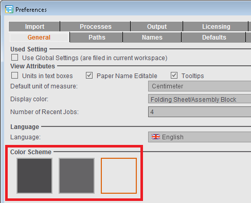
The user interface can be viewed in three different designs. You must restart Signa Station after having made your changes. See also Concept of the User Interface .
Use Command Key + Spacebar for Zoom
When the option is enabled, the "command key + spacebar" shortcut known from old versions is used again for zooming and the "command key + E" shortcut for operation of the workflow bar.
The new default is applicable if the option is not enabled:
•"command key + spacebar" -> operation of the workflow bar
•"command key + E" -> operation of the zoom tool
You will find more keyboard shortcuts in Keyboard Shortcuts.
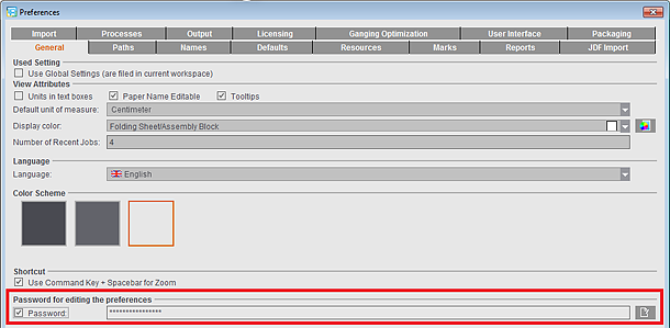
Password for editing the Preferences
You can assign a password to prevent unwanted changes to the Preferences. Users who open the Preferences without entering a correct password cannot save their changes. In this case, the "Save" and "Reset" buttons are dimmed.
Enable "Password". The dialog for assigning a password opens automatically where you have to enter your password twice for security reasons.
While the Preferences are open, you can edit the password without entering the password already assigned. After you save and close the Preferences, the password is requested the next time you open the Preferences, and it is not possible to save changes to the Preferences without entering this password.
The prompt when opening the Preferences also appears even if only the option was enabled and no password entered. The password box then stays empty.
To edit an existing password, click the Edit button to the right of the text box. Then you must first enter the password to date and the new password twice in the other boxes.
During a PDF import (page assignment) a check is run on the values entered in this box. A message displays if the difference between the PDF layout page that will be imported and the defined trim box is out of the tolerance range.
You can enter the maximum differential values in x and y direction that are tolerable.
The differential values are checked when the pages are being assigned, and a warning is issued if the values are exceeded or if they fall below the set amount. You can cancel page assignment or continue with it nevertheless, depending on how you reply to the message.

Note: The values are used also for the import of gang jobs with sheet optimization to check whether a job fits into the layout default. As a result, sheet optimization with a layout may no longer be possible if "0" is entered as the value in "Maximal Difference". For that reason, the smallest permissible value is entered automatically if "0" is entered.
In many message windows, you can choose not to display the message again by enabling the "Do not show this window again" option. All message windows suppressed in this way are displayed in this list in Preferences.
In addition to the message ID, the list contains the message text and the setting, i.e. which button in the message was last used to close the message window. This setting is then used by default.
If required, individual or all message windows can be reactivated in order to be able to choose between different options again.

Note: The Prinect Signa Station Server (or the SignaGangServer) itself does not have a user interface and therefore does not display any message windows by default. Message windows that appear in the server during job processing are automatically "answered" with the respective default setting. If you wish to deviate from this standard response, you must edit the message list on a Signa Station running on the same computer as the Prinect Signa Station Server and using the very same workspace. By clicking on the additional button "Transfer to server", all entries in the list are immediately transferred to the server. A confirmation message then appears.
The preferences defined in "Paths" save you unnecessary steps when you are saving and opening files. In addition, you can define a path to Acrobat Reader to start this application automatically whenever it is needed.
The path and folder set in "Workspace" defines where the resources folders are also filed.
If you change the default "Workspace", the resources included in the shipment in the "Standard" folder are copied to this new workspace. Any user-specific resources remain in the old path structure and can no longer be seen or selected in Signa Station.
Set the other folder paths to suit your needs. Click the folder button and select the folder you want. By default, data are opened and saved from the set folder path.
Example:
The folder that you set in the "Paths" tab in "Jobs" appears by default when you select "File > Open".
You can also define the path to Acrobat Reader here for viewing PDF files.

Note: Using the folder button, define the path to Acrobat Reader. Select the respective ".exe" file.
You can also type the path directly into the text box. The Preferences cannot be saved if there is an invalid input.
In the "Names" tab, you can set custom names as defaults in certain cases. These are then used by default by Signa Station.
In addition, it's also possible to modify and/or define default names and attributes.
In the "Name" column, double-click the row with the index you want to change and type the new name of that layer.
Example of a bilingual document with language-independent images:
|
Index |
Designation |
|---|---|
|
1 |
Images |
|
2 |
German |
|
3 |
English |
The procedure for showing layers is described in View Properties and Enable/Disable Layers in the Graphic Window chapter.
You can overwrite each of the default names for example, for "Versioning". More details can be found in Level.
In Sheetfed Press
You can overwrite each of the default terms "Front", "Back", "Single-sided", "Work-and-turn" and "Work-and-tumble". The terms are used in the graphic window and for output.
The names are also written to the JDF in the JDF workflow.
In Web Press
You can overwrite each of the default terms "Top", "Bottom", "Work-and-turn" and "Work-and-tumble". The terms are used in the graphic window and for output.
The names are also written to the JDF in the JDF workflow.
Placeholders
In the list box, you can select placeholders that are to be part of a file name. The placeholders you selected are used when you click the "Insert placeholder" button. Placeholders "Job Number" and "Job Name" are set by default. When you save your job, the placeholders are replaced as specified in the job, and the name is set automatically.
The names are evaluated in the JDF workflow with the Prepress Manager.
More details can be found in Full Job Name in the Job Inspector.
•"Create a generic product part name"
An abstract product part name (TP01, TP02, etc.) is created in the output file instead of the product part name if you enable this option.
This option has no effect in the JDF workflow with the Prepress Manager.
You can insert additional information on the sheet with the help of freely configurable replacers. You can define general, job-specific replacers (features) that can then be filled with data in the "Attributes" tab in the "Job" step. You can define up to 99 freely configurable replacers.
You should define the replacers before you open a job. When you open a job, the replacers are then defined in the "Job" step.
See Job (Attributes) for details on what to do next.
This option has been added especially for the interactive variant of the "Versioning" workflow.
Characters used for each version in the variant name
When you create press sheet variants with different versions, their names can be very long, something which may cause errors during further processing.
With this setting, you can define the number of characters of the version names that will be used to create the variant name.
In Signa Station, the variant name is used in the view and for placing marks, and it is also written to the JDF for PtR output.
The following settings are possible:
•"1-5" = constant number of characters that will be taken from the version names
•"In full" = all original version names are kept as the basis.
•"Optimal Shortening" = automatic feature that compares all the current version names and shortens them uniformly so that the names are still unique.
Use 'Version Description' for Name
The version name is often not very informative. You can use the version description instead of the version name for displaying the file because this version description that is also available in parallel in most cases is not subject to the constraints that are valid for the version name.
However, the option works only if the version descriptions can be used for unique identification. This means that all version descriptions must be
•available
and
•different.
This tab shows you typical defaults for the functions usually used. The defaults are only meant to simplify your work and can be changed at any time later in the job.
You can also set options for special functions that simplify or automate a certain procedure.
Bleed
The default for the bleed is 3 mm.
You can find more details about bleeds in Master Pages.
in routing margin
Prerequisite: Perfect binding is chosen as the binding method.
You can change the bleed in the routing margin. This enables you to handle the special requirements of different gluing techniques.
Negative values produce a "colorless" area at the routing edge of a page.
Defaults for folding sheet generation
Minimum and maximum routing margin
The routing margin defines the space that is required only in perfect binding to get a "smooth" gluing edge.
The default for the "minimum routing margin" is 2 mm and for the "maximum routing margin" 3 mm.
You can find more details about the routing margin in Use routing margin.
Minimum/Maximum Foot/Head Trim/Gap
The defaults define the minimum/maximum possible spacing of the gaps on a folding sheet.
These defaults are applied when you use the "Automatic Gaps" function in the "Schemes" step.
You can find detailed information about gap calculation in: Overview of Gap Computation
Min. Gripper Fold Values / Max. Gripper Fold Values
By setting minimum and maximum defaults for front fold and rear fold, you confine the gripper margin to a reasonable range, matching the saddlestitcher used in finishing.
The minimum value is set with the "Gripper Collator" function in the "Binding" step. It is no longer possible to enter a value higher than the maximum.
Paper Thickness Factor
Paper thickness is used as the default for automatic calculation of creeping. You can change the value manually in the "Binding" step.
In automatic gap computation, this parameter defines an unused area at the top edge of the paper. The area available for automatic gap computation (normally this is the width and height of the paper) is shortened in height by this value. The gaps are calculated to fit on the smaller area.
Because of the possible tolerances with different paper suppliers, it is best to specify this border for portrait orientation. To be then able to have a precise head trim at the top of the pages. This should always be cut.
Scheme filter
Only schemes that fit on the paper and where the number of pages is less than or equal to the number of unplaced pages are displayed for selection.
You can disable the filter later when selecting a scheme, for example, using the "Schemes" step.
One Folding Sheet per Sheet
The "One Folding Sheet per Sheet" option is the default for the same option in the "Schemes" step > "Press Sheet Layout". See One Folding Sheet per Sheet for details.
You can change the folding sheet order for better pagination in the "Schemes" step > "All Folding Sheets". This change also changes the press sheet order. Enable this option if you wish to keep the press sheet order unchanged.
Restrict 'Apply' functions in Page Inspector
In some cases, it may not make sense to apply placement rules and marks to all pages in the job. When this option is enabled, you can restrict the function to the pages of the currently active folding sheet/assembly block.
Use Media Box for Positioning
Normally, when you import a PDF content file that has a trim box (equivalent to the "trimmed size" in Signa Station), positioning is based on this trim box.
However, enable this option if you prefer to use the media box as the basis for positioning your data.
You cannot enable this option in a Prinect workflow.
For more information, see the Glossary and the Placement rule for assigned pages.
"AutoArrange" after Plate Loaded from Product Part Template
Prerequisite: Both product parts must be gang run forms. The "Gang run form" option must be set in the "Plates" step.
During an import, the option automates the "AutoArrange" button in the "Schemes" step > "Press Sheet Layout". For a description of this function, see Position and orientation of folding sheet 1up (gang run form only).
Automatic lock for Product Part Inspector
A currently selected product part is locked automatically by Signa Station when you make custom changes to it (e.g. in the Press Sheet Inspector).
If the option is not set globally in the Preferences, you can still set it separately for each product part in the "Product Part" step.
You can find more details on the functionality in the "Product Part" step in No-change lock.
Preset margins of new assembly blocks with bleed value
When this option is enabled, the margins of new assembly blocks are set to the default bleed (see above) if they are created without a template (= no assembly block is selected). The margins are set by default to '0' if the option is disabled.
Create Versions with Base Layer
When you use versioning, the different versions are by default generated as a combination of the base layer and the follow-up layers. To create versions without base layer, you can use the function "Define Versions without Base" in the "Version Editor". To create the versions without base layer by default, disable the option "Create versions with base layer" here in the Preferences: Although being present, the base layer will not be assigned to any version.
This setting also applies when importing an MIS JDF.
Center subject
The subject is centered in all directions relative to the paper when you select "Sheetwise (front and back)" as well. The lower edge of the subject with the bleed offset is positioned on the lead edge (blue line) when this option is disabled.
In the "Packaging" or "Ganging Optimization > Sheet Optimization for Packaging" work mode
Make subject settings in the "Plates" work step as follows:

|
If the "Center Subject" option is enabled in the Preferences, the "Center cutting dies on the paper" setting is used. All the cutting dies are distributed evenly in each direction and centered as a whole to the paper or half of paper. If this is not possible because there is not enough space, then the cutting dies are arranged one below the other and centered to the paper or half of paper. |

|
When the option is disabled, the "Center cutting dies horizontally on paper and vertically on the gripper edge" setting is used. |
See Points to note for "Plates" in the "Packaging" or "Sheet Optimization" mode
In the "Ganging Optimization> Sheet Optimization without Layout Default" work mode
Make subject settings in the "Plates" work step as follows:

|
"Center Subject" option enabled in the Preferences: The subject is centered horizontally and vertically, regardless of the placement defaults in "Optimization > Advanced Settings...". The centering refers to the range specified by the margins in "Geometry Data for Sheet Optimization". |

|
"Center Subject" option disabled in Preferences: The subject is centered horizontally, referring to the range specified by "Margin left" and "Margin right". The vertical position is - according to the placement defaults - within the range defined by "Top Margin" and "Bottom Margin" in "Geometry Data for Sheet Optimization". |
See Points to note for "Plates" in the "Ganging Optimization" mode
Consider Gripper Margins and Non-Printable Margins
During the automatic calculation of the number of 1ups, this includes the gripper margin and the areas for lead edge of print and tail edge of print as well as the margins on the side as set in the machine parameters. A warning will be issued if subject, folding sheet, bleeds or marks are found in one of the critical areas during printing. You can enable/disable the option for a specific job also in the "Plates" step (see Subject Settings).
Subject-Clipped Marks Centered on Plate
Color control marks with enabled "AutoClip" are automatically centered on the plate.
Invert Print Order of Marks
By default, the marks are printed in the following order:
1.Page-related marks
2.Folding sheet-related marks
3.Subject-related marks
4.Paper-related marks
5.Plate-related marks
This means that the plate-related marks are printed over the other marks.
When this option is enabled, the marks are printed in exactly the reverse order, in other words, the page-related marks are printed over all the other marks.

Note: The other preferences for handling marks are set in the Resources as automarks sets (for a description, see Automarks).
•Increment (Offset)
Defines the distance you move objects in the graphic window each time you click an arrow button, e.g. when moving assembly blocks.
Default: 1 mm per step (click on arrow key)
•Increment (Scaling)
In the "Press Sheet Inspector > Marks", this defines by how much a value is changed each time you click an arrow button when scaling marks using the arrow buttons.
Defaults for Master Pages (Placement Rule)
In the available work modes, you can set the placement rule by default when assigning pages/1ups. You can choose between "From Trim Box" and "Center".
You can find more details about the placement rules in Placement rule for assigned pages.
The default for the "Imposition/Automatic Imposition" work mode is "From Trim Box", and the default for the "Packaging" and "Montage" modes is "Center".
You will find an illustration of the function in the "Packaging" or "Assembly Block" steps in "Placement rule for assigned 1ups".
You can define defaults in the "Resources" tab that Signa Station will then automatically draw on.
Default
The setup has no defaults when you create a new job.
Job Template
When you create a new job, the job template selected in "Choose Job Template" is used by default in the workflow bar. You can invoke this function also directly in the context menu in the Browser window. See Job Templates for details.
Product Part Template
When you create a new product part template, the product part template selected in "Choose Product Part Template" is used by default in the workflow bar. You can invoke this function also directly in the context menu in the Browser window. See Product Part Templates for details.
Reader's Spread Template
You can use the "11x17-TwoUp (ReadersSpread)", "A3-TwoUp (ReadersSpread)", "A3-TwoUp-Collating-Mix (ReadersSpread)", "A4-OneUp (ReadersSpread)" and "Letter-OneUp (ReadersSpread)" product part templates for converting your data to reader's spread. These templates cause the defined master pages of the product part to be converted to reader's spread when you select "Product part in reader's spread". For more details, see "Product Part in Reader's Spread / Product Part for Single 1up Proofs".
You can select product part templates especially for packaging printing. For more details, see "Product Part in Reader's Spread / Product Part for Single 1up Proofs".
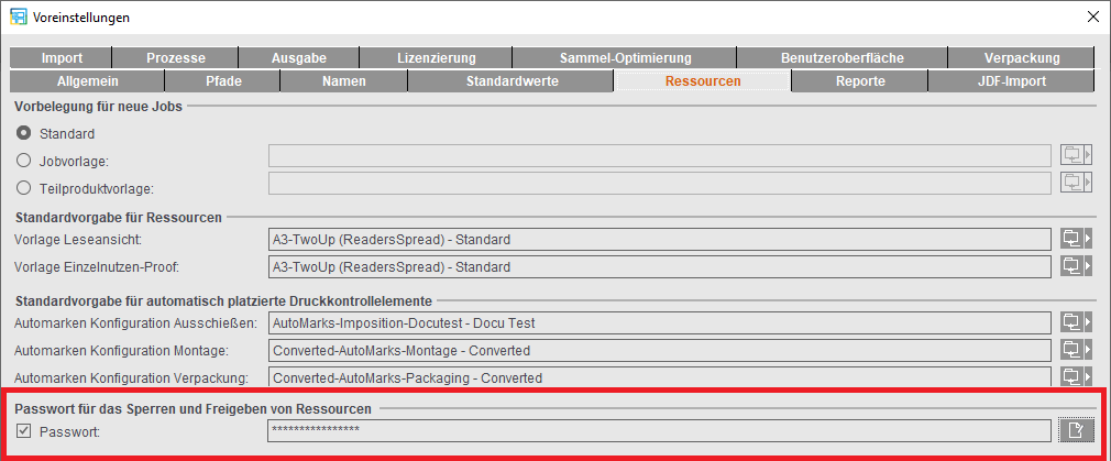
Default for Automatically Placed Print Control Marks
"Show all used automarks in a table": When creating new jobs, the "Marks" step in the table displays only the automarks used in the job. This simply means that the filter is enabled by default for a better overview. If necessary, the filter can be disabled in the job so that all automarks of the automarks set are displayed
In the Resources, you can create different setups for automatically placed print control marks. This is where you select for each work mode which automarks set will be used as the default when creating a new job. In the job itself, you can select a different set, if required, or edit the set specifically for the job.
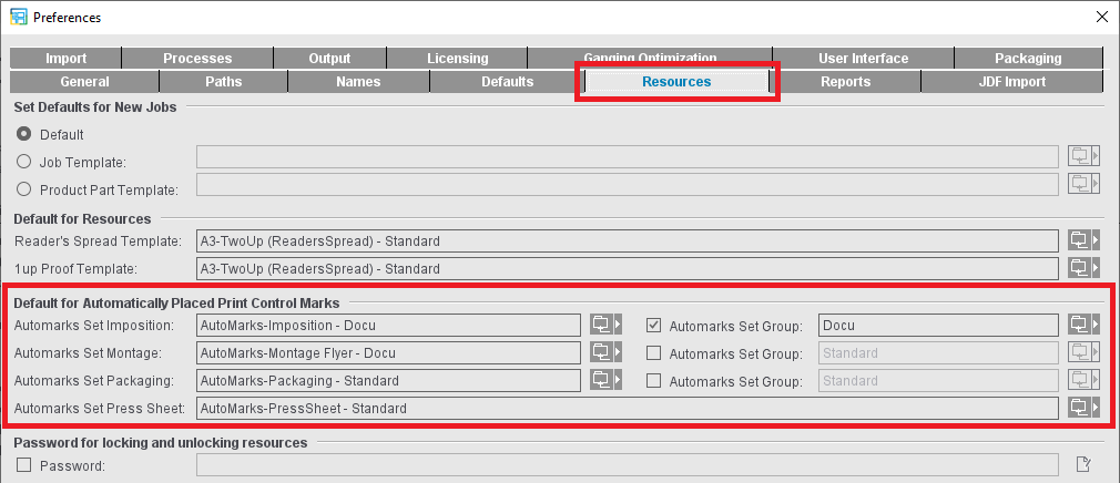
At present, the following kinds of automarks sets are available:
•Automarks Set Imposition
•Automarks Set Packaging
•Automarks Set Montage
(all three folding sheet-related)
•Automarks Set Press Sheet
Depending on the work mode, you can also specify that all automarks sets of a certain Resources folder will be copied to the new job created. These automarks sets are listed and browsed in alphabetical order in the table below "Marks"; the selected default automarks set is always inserted at the end of the table.
You can find detailed information about automarks sets in: Automarks
Password for locking and unlocking resources
To prevent unwanted changes to the resources, you can lock single resources or whole resource groups. You can assign a password in this part of the Preferences to lock and unlock resources.
Enable "Password". The dialog for assigning a password opens automatically where you have to enter your password twice for security reasons.
While the Preferences are open, you can edit the password without entering the password already assigned. After you save and close the Preferences, the password is requested every time you lock or unlock resources or resource groups. As a result, changes to the resources are possible only if the user knows the password or if the resource is not locked.
The prompt also appears even if only the option was enabled but no password entered. The password box then stays empty.
To edit an existing password, click the Edit button to the right of the text box. Then you must first enter the password to date and the new password twice in the other boxes.
Signa Station provides you with several options for creating reports of jobs and product parts to document and/or check a job:
•In the Browser window using the context menu (jobs and product parts). More details can be found in Functionalities Relating to the Job.
•In the list window using the context menu of the various tabs with the appropriate job data (product parts only). See Context-sensitive menu functionality for details.
•In the Output Parameter Set Editor, a report can be created automatically with the "Create Reports" option. You can set this in "Output Parameter Set Editor > Report > Create Reports".
•It is also possible to define in the output parameter set editor that MSO XML reports are generated and stored in the gang pool ("Work&Done") as well. See ’Report’.
In a job with sheet optimization, you can display the result after optimization as HTML in the default browser by clicking the "Report" button.
•For JDF output, reports can generally be created via the "Automatic Reports for JDF Output" option in the Preferences and also stored in the output folder (in the so-called "JDF suitcase").
•With "Additional output folder for XML reports" a central folder can be defined where all MSO XML reports are stored, for example to facilitate evaluation. This is possible regardless of whether the JDF output options are enabled in the Preferences or in the output parameter set.
The reports in this output folder are named according to the following scheme:
MSOReport_job_name.xml
The job name is created according to your specifications in "Preferences > Names > Job File Name".
Standard report items
In addition, you have the option of defining barcode marks and then sending them to finishing with "Save Table as HTML File...". At the saddle stitcher, the feeders can then be loaded fully automatically.
Procedure:
1.Position the "WST-5-Barcode" default mark on the relevant folding sheets.
2.Go to the list window and select "Select Columns" in the context menu (mouse pointer to table header).
3.Add the three WST marks below "Report" with "Add Mark".
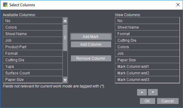
4.Confirm the window and send
the HTML report to the "WST Control Client" for finishing with "Save Table as HTML Report ...".
We will now describe the many options you have when creating your reports. In Preferences, you only set the defaults for reports. When saving a report, you can always change the defaults for this report using the "Report Options" function.
See Context-sensitive menu on items in the table (all lists) for output of the reports.
This is where you set the defaults that will be in the files when the reports are output. See "Save Table as HTML Report ...", "Save Table as PDF Report ..." or Create Reports for output of the reports.
Report header
A cover sheet precedes the job data in the reports. This is defined by the default "ReportHeader_en.html" file (includes variables such as job name, customer name, page total,...).
You can define a custom report header with the Report Templates Editor. See Report Templates Editor. After you defined it, you can then select it in this tab.
Header
In addition to the report header, you can also add a header to the beginning of the report by selecting a mark.
Company logo
Besides the report header and header, you can also assign a graphic file to the reports by selecting a ".png" graphic file with the company logo.
This is where you define the defaults for labeling and/or displaying preview images in the reports. In addition, you can also include certain view properties from the graphic window in the reports.
See View Properties and Enable/Disable Layers for details on setting view parameters in the graphic window.
Surface header, surface footer, preview size
You can label press sheets in the print report by selecting and positioning marks. You can also define the size of the press sheet preview images.
Dimensioning
All units of measure set in the graphic window are written to the report.
Symbols
All icons set in the graphic window are written to the report.
Gang run form layout for gang jobs
When this option is enabled, information and layout of the placed 1ups display in the report and not contents, irrespective of the graphic view currently selected in the job. See also 'Gang Run Form Layout' .
Use graphic view setting
The setting defined in the "View" tab in the graphic window displays for the report. See 'View' for details. The other three options are disabled automatically here in the Preferences.
You can add right, left and centered footers to the reports by selecting marks.
The "Page and Paper Sizes" you want are added to the reports when you select them.
Attributes for Report Handling
Reports with Preview
The press sheets in a job are written as a preview image to the report.
The report contains the HTML/PDF file with information about the job and image files (*.png) with the press sheets available in the job.
With this option disabled, a simple HTML/PDF file is written only.

Note: Disabling the option is sometimes necessary when working with a saddle stitcher and barcode reader. A description of this can be found on the next page.
Limit Preview to Different Press Sheets
When this option is enabled, a number of identical press sheets display only once as an image file in the report to save space. The number of identical press sheets is indicated by a digit.
Automatic Reports for JDF Output
Reports are written automatically when JDFs are output. A "report" folder is created in the output path, and the report of the job is filed in this folder.
Always Show Last Configuration in Save Dialog
When this option is disabled, the defaults currently set are used for creating the report.
When this option is enabled, the job settings last saved in "Report Options" when creating a report in the "Save as HTML/PDF Report" window are used.
Creating Simple HTML Reports When Evaluation Problems Occur in the WST Barcode Reader
An HTML report is created for saddlestitchers centrally controlling the barcode readers of all stations with a console. Signa Station writes control data for the barcode readers into the exported file. Expecting this file in a particular location, the saddle stitcher console will then parse it.
As the reports currently generated by Signa Station require additional data (such as previews, report header, company logo, etc.), they are stored in folders. This can lead to problems during evaluation by the WST barcode reader. For this reason, there is an option of creating a simple HTML report with Signa Station:
1.In "Preferences", tab "Reports", disable the option "Reports with Preview".
2.In the Browser window, open the context menu on the job and choose the function "Save Job as HTML Report".
The simple report does not contain preview, report header, company logo, etc., but the table only.
This is where you can set the default for the product part template, especially for JDF import. This lets you choose a template for JDF import that is different to the one specified in "Product Part Template" in the "Resources" tab.
Use Template in Extended Mode
Checks various parameters and prioritizes the settings in the template if the parameters match the JDF data.
If the parameters match, only "Administrative Data" like "Customer", "Job Number", etc. are taken from the JDF, all other parameters do not change. The product part extends the page count automatically.
Prerequisite: The "Match Folding Sheet Count to Page Total" option must be enabled in the template.
Default for Product Codes Search
Use this feature to set the basic group for looking for product part templates for JDF import. This folder is used for gang run jobs and Web to Print.
Resources Default for JDFs with Job Prep Data
The output parameter set defined in this box is used automatically if the "Complete Layout" function was used in the Prepress Manager. When this function is set, the layout is generated automatically after the JDFs are imported from the Prepress Manager and is sent back to the Prepress Manager without any manual intervention.
Resource Group Default for Search

Note: When importing JDFs, only these resource groups are searched, not all the other resource groups in the system if no match is found in the first place. An error message is issued if a matching item is not found in the groups specified here.
Plate template
This is where you define the folder where Signa Station looks for a suitable plate template during a JDF or Signa 9 Template import. The plate templates in this folder are scanned in the listed order. The following JDF items are supported in this process:
•"FriendlyName"
•"DescriptiveName"
•"DeviceType"
•"DeviceID"
A comparison is made to see
1.whether the name in the JDF exactly matches the name of the plate template resource or the name of the machine set in the resource or
2.whether these names are part of the string in the JDF.
Whenever a matching item is found, this plate template is used and the list is not scanned further.
If a matching item is not found in the whole list, the smallest possible plate template matching the set paper size is used.
Example:
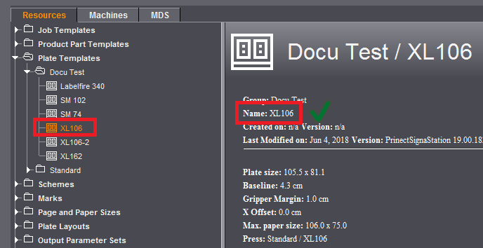
In the JDF, "XL106" is set as the "DescriptiveName" and "DeviceType". "Docu Test" is set as the folder for the search for suitable plate templates.
In the first example, an "XL106" item is found in the list whose "name" exactly matches the requirement from the JDF. The "XL106" plate template is used; the "XL106-2" that possibly might also be suitable is not checked because it is further down in the list.
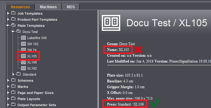
In the second example, an "XL105" item is found in the list whose "name" "XL105" does not match the requirement from the JDF. This requirement is met only with the next item "XL106". In the "XL105" plate template, however, the information for the "press" matches with "XL106". This means the "XL105" plate template is used because "XL106" that matches by name is further down in the list and is not checked.
In other words, you must make sure that the names of the plate template or the press in your MIS system matches the names in the resource group. If you do not use custom plate template resources but the standard folder included in the shipment, single resources might no longer exist under the same name following a program update.
We recommend that you create a custom folder for the resources you use and define custom plate templates there or save copies of the plate templates from the standard folder there.
Click the folder button on the right and select the folder you want. The "Standard" folder is set by default.
Scheme
This is where you define the folder where Signa Station looks for a suitable scheme during a JDF or Signa 9 Template import.
Signa Station will then explicitly search this folder and its subfolders. An appropriate scheme according to "Folding Type (CIP4)" is used if a scheme with exactly the same name is not found. Other folders parallel or at a higher level will not be searched.
Click the folder button on the right and select the folder you want. The "Standard" folder is set by default.
Calculate Automatic Gaps
If this option is checked, Signa Station uses product-specific algorithms to check the JDF data and correct any errors.
The data from the JDF are used as they are if this option is disabled when you import JDFs with internal "stripping params" (from job preparation).
Default: The option is enabled to correct any errors in the JDF.
When the option is enabled, you can also select whether the values specified by the MIS for the inner trim allowances (e.g. routing margin) and/or the bleed are to be used.
The positions of the folding sheets are calculated automatically by Signa Station when JDF files with gang run forms are imported.
Special Interpretation of Folding Sheet Orientation
It can be wise to enable this option when importing JDF files from third-party MIS systems. The folding sheets are then oriented automatically by Signa Station.
Constant Press Sheet Order for JDF Import (recommended: On)
This option is similar to the one in "Preferences > Defaults" but can be set independently of this, i.e. you can make different settings for the creation of jobs with or without prior JDF import. The option automatically selects the appropriate procedure when importing from an MIS system. For an explanation of this function, see Constant Press Sheet Order .
Show warnings if plausibility check fails during output
During the output of imported MIS JDF files, messages are issued, indicating the changes to the imported JDF after processing by Signa Station (e.g. change of press, modified sheet name).
Automatic Page Assignment for New Jobs
When this function is enabled and a new layout is to be created from the Prinect system, the Signa Station will assign the pages automatically if the following conditions are met:
•a new layout must be created
•when the layout was created, the PPM did not provide a page list
•the PPM job must come with content data
•there must be only one content PDF (for each version in case of versioning), and the number of content pages must equal the number of possible layout pages.
Any warnings will also be displayed (e.g. when the page geometries differ).
Default setting: Option is disabled.
Ignore Cover of Product Part Template if No Cover in JDF
In an automated workflow, product part templates are used to define the layout that will be generated. One of the things that the product part templates offer is the option of defining a folding sheet for the cover. If products are to be created that only differ in whether they have a cover or not, you do not have to create two separate product part templates for this.
If this setting is enabled, the first scheme will be ignored if no cover is specified in the JDF when you are processing a JDF with a product part template where "First Folding Sheet is Cover" is enabled.
This setting affects only product part templates where "Match Folding Sheet Count to Page Total" is enabled.
You can define machines, separated by commas, where there will be no automatic gap computation.
The "JDF Import" option must be licensed in "Licensing" before you can create and use any rules.
Use Rules
This enables the functionality globally.
When you enable the option, the rules defined in the Rules Editor are applied.

Note:
In the field, disabling this option can be a good idea, though, to allow JDF imports without using rules.
Path to rules
Displays the name of the path where the set rules file of the Rules Editor is located.
The folder button lets you not only edit the "default folder" but also select a different one.
Start the JDF Import Rules Editor
Clicking this button closes the Preferences and then starts the Rules Editor; for more details see the description in JDF Import Rules Editor... .
This is where you set the path to the input folder for JDF files. Files copied to the hotfolder are processed automatically by Signa Station. You can view a list of the JDFs in the hotfolder with the "Tools > JDF Jobs Status" menu command (see JDF Jobs Status... ).
Use MDS
Connection to an MDS is possible if you are working with the Prepress Manager and an MDS is installed. Type the name of the server on which the MDS is installed.
Working with an MDS lets you access central resources in the network from your workstations.
The "Customer Data", "User Data", "Filmsetters", "Platesetters" and "Sheetfed/Web Presses" resources are available through the MDS but can only be viewed in the respective editor. It is not possible to edit these MDS resources with Signa Station.
You can edit the "Papers (Printing Materials)" resources in an editor analog to the Printing Material Editor in Cockpit (see Paper (Printing Material) Editor).
Local resources for the "Platesetters", "Filmsetters", Sheetfed Presses", "Web Presses" and "User Data" resources are available in addition to the MDS resources.
Resources from MDS can be found in the "MDS" tab, item "Resources & Machines" and are usually displayed in a table because this view proved to be the clearest format.
Encoding
PDFs can have different types of encoding. You can set a default encoding type in a list box for correct interpretation.
Show Spot Colors as True Colors
Prerequisite: MDS (Master Data Store) is enabled.
Spot colors are shown as true colors if color tables for the spot colors are defined in the MDS.
The "Overprint Settings" defined in the PDF are also calculated and shown.
Preview with Transparency
The transparency elements in the PDF display.
Limit Previews to 100%
The preview images are scaled up to 100%.
One Page per Color in Separated PDF
When this option is selected, each color separation (CMYK and any spot colors) becomes a single document page. Color separations are not combined to form logical pages.
The licensing window displays when you first start Signa Station.
To add to or change your licenses and options at a later period, you can make your changes in the Preferences in the "Licensing" tab. The changes are enabled when the system restarts.

Note: In an upgrade, the license configuration of the predecessor version is applied automatically. There is no license request. In this case, the basic version is applied as it is and all available additional options that have at least a floating license are also enabled. In the case of licensing conflicts, these license options may have to be disabled again.
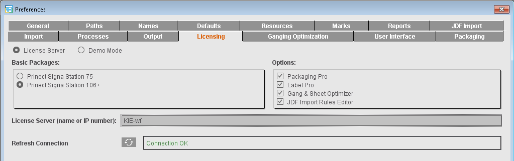
This option is set by default and lets you install a full version of Signa Station. You must have a valid license for this.
The entire software functionality is available to you in the demo mode. You can put the software through all its paces and only then decide if you want to acquire a license.
It is not possible to output a job. When you save demo jobs, they will be marked so that you cannot output any of the jobs you created.

Warning: You can open jobs from the full version of Signa Station and change them but you cannot output them again once they are saved in the demo mode. You should not open your production jobs with the demo version.
License Server (name or IP number)
A HEIDELBERG license server must be installed on your computer or in the network to be able to run Signa Station. Type the name or IP address of this license server into the box.
Shows connection status to the License Server. You can refresh the display if necessary.
Select the basic package you have a license for. The following packages are available:
•"Signa Station 75": The printing plate width is restricted to 83.5 cm. All output formats are available to you (PDF, JDF, Adobe Portable Job Ticket Format (JT)).
•"Signa Station 106+": The printing plate width is restricted to 600 cm. All output formats are available to you (PDF, JDF, Adobe Portable Job Ticket Format (JT)).
•"Prinect Signa Station Server": The printing plate width is restricted to 600 cm. Only the JDF and JT (Adobe Portable Job Ticket Format) output formats are available to you.
You may use this variant only in a workflow with the Prepress Manager.
A layout can be put together automatically by all the Prepress Manager Cockpits without having to operate Signa Station interactively.
Select the option matching your license. Multiple selection is possible. The following options are given:
•"Packaging Pro": Has all the editing and animation functions needed for the "Packaging" workflow (see the Packaging (Packaging Pro, Label Pro)).
Signa Station Packaging Pro is a special CAD module that lets you import various CAD and vector graphic formats, edit issues in drawings, modify the sheet layout, create clip paths and preset finishing equipment such as folder-gluers, etc. Signa Station Packaging Pro was designed to add high-quality, specialized packaging features into Signa Station.
•"Label Pro": Has all the functions needed for the "Label Pro" workflow.
Signa Station Label Pro is a good add-on module for Signa Station Packaging Pro for editing labels. A Label Pro license extends the scope of Packaging Pro but can also be acquired as a separate item.

Note: Packaging Pro and Label Pro are described in their own Online Help.
•"Gang & Sheet Optimizer": This option makes it possible for you to create a gang job ("Ganging Optimization" work mode) using sheet optimization (see Requirements for Creating a Gang Job for details).
•"Ganging with Segments for Finishing": Additional option for the "Gang & Sheet Optimizer" license; during ganging optimization, segments help you group elements with the same finishing on the sheet. This option can be seen only if there is a license for it on the License Server and it can be enabled only if the "Gang & Sheet Optimizer" option is enabled.
"JDF Import Rules Editor" is a rules editor for creating special rules that are applied when you import JDF files (see the JDF Import Rules Editor... ).
In the "Ganging Optimization" tab, you set the default templates for sheet optimization, the default product part template for product codes search and the default folder for the gang parts that will be imported to a gang job.
Default for Sheet Optimization
This is where you can set up which assembly blocks will be used automatically when you create a new product part in the "Sheet Optimization" work mode.
By clicking the respective button, you open either a dialog where you can select the product part template you want or you select one from a list with product parts that you selected beforehand.
Sheet Optimization Setup Template
The template set here is used as the default for working in the "Montage" and "Packaging" mode with the "Sheet Optimization" option enabled and for the gang job workflow. The default template used depends on the work mode selected.
Default = MSO (displays in the "Optimization" step for "Montage" and "Gang Job")
Default = MSO_Packaging (for "Packaging")
Template for Assembly Block
To select a template, click the right folder button. You can select only product parts of the "Montage" work mode.
"Product Code for Assembly Block": The product code is used as the default for assembly blocks in sheet optimization with segments.
Template for CAD Assembly Block
To select a template, click the right folder button. You can select only product parts of the "Montage" work mode. The selected template is used as the default for a CAD assembly block in sheet optimization.
"Product Code for CAD Assembly Block": The product code is used as the default for CAD assembly blocks in sheet optimization with segments.
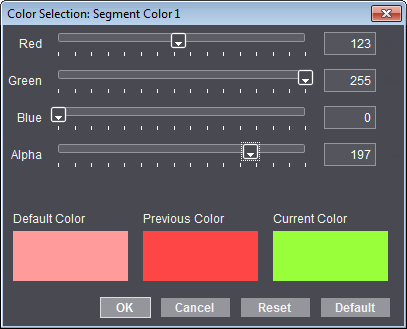
Display color
In addition, you can define the color that is used to display the segments in the graphic window. This requires that the "Segments" option is enabled in the display settings.
In the Preferences, you define the colors and assign segment numbers. In the resources, you can then assign these segment numbers and their colors to the segment templates.

|
To edit the colors, select the segment color you want to change from the list and click the button with the color icon. |
The "Color selection: Segment x" dialog then displays, where you can set the color you want using the slider or the text boxes. "Default" lets you reset the color values back to the original default settings, use "Reset" to restore the values last saved for a color.
Default for Product Codes Search
Use this feature to define the base group for the product part template search. In this group, the gang parts are scanned for product codes during ganging optimization. This setting affects jobs with sheet optimization. For JDF import, you can set the base group separately in the "JDF Import" tab.

Note: You can also set the defaults for the assembly blocks and the search for product codes for a specific job in the "Product Part" step.
If the default is changed, this does not affect existing jobs. These jobs keep their setting for the base group for the product part template search, irrespective of whether there was a specific setting in the job or whether work was based on the default applicable at the time the job was created.
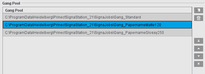
This is where you select the folder from which the gang parts will normally be imported for a gang job. This folder is then set when the "Job Import from Gang Pool" window opens. You can modify the default for a specific job by selecting a different folder in "Start Conditions" in the "Product Part" step. If the default is changed, this does not affect existing jobs. These jobs keep their setting for the gang pool, irrespective of whether there was a specific setting in the job or whether work was based on the default applicable at the time the job was created.
You can also create multiple gang pools to pre-sort jobs, for example by paper type. This reduces the time it takes to open the "Job Import from Gang Pool" window if there are many files in the gang pool.

|
Add a new gang pool to the list (a browser window opens in which you can select the desired folder and add it to the list by clicking "Apply"). |

|
Remove the selected gang pool from the list; the gang pool is not deleted from the file system, but any jobs it contains are no longer offered for import. |

|
Move the selected gang pool up or down one position in the list (multiple selections possible); the top folder is the default folder. |

|
Move the selected gang pool to the first or last position in the list (multiple selection possible). |
The MSO XML report can be written to the JDF output directory (defined in the output parameter set under "General > Output folder for JDF, PDF, JT...") as well as to the job directory in the gang pool in a subfolder of "Work&Done" (defined in the output parameter set under "Report > Automatic XML Reports for JDF Output"). Here in the Preferences, you can additionally define a fixed folder where copies of all MSO XML reports are saved (e.g. for automatic evaluation).
A login dialog always appears for logging in to Signa Station.
When you log in the first time, use the default user "Signa" and the password "signa".
Proceed as follows to change the user:
1.You assign user permissions and change users in "Jobs & Resources > Resources & Machines > User Data".
2.Mark the "Signa" user in "PrePress Administrators" and display the context menu.
3.Click "Edit User Data..." to change the default user.
4.Type in the user name you want and repeat your password twice and then click "Save".
You will then see the changed user in the list of defined "PrePress Administrators". The user has the permissions of the "PrePressAdministrators" group.
To avoid the login dialog appearing every time Signa Station launches, you can set an automatic user login:
•In "File > Preferences > General > Default User", enable the check box and select a user. After this, the login dialog no longer appears.
To make the user interface clearer and easier-to-follow, all preferences possible that can be seen, expanded or collapsed in the user interface or are required only for certain workflows were moved to the "User Interface" tab.
This functionality is designed to make configuration of the user interface even more user-friendly.
There are a number of parameter sets showing useful combinations for certain workflows. In particular, the "Big Jobs" parameter set ought to be included when PDF-VT files are used. However, these preferences are only suggestions and do not have to be selected. You can create a new parameter set by clicking "Create new parameter set" at the bottom of the tab. You can then modify this parameter set as required
Controls can be used in the user interface when the relevant items are enabled in the "visible" column.
More extensive controls display in the user interface when the relevant items are enabled in the "expanded" column. You can save space and only the header is shown if they are disabled. If necessary, you can expand the control manually.
Configurable elements in the user interface
Job Details in Product Part
See Job Details in Product Part for a description of the function.
Segmented Folding Sheets
See Segmented Folding Sheets for a description of the function.
Custom Bleed Values
See Custom Bleed Values for a description of the function.
Default for JDF and job ticket (third-party workflow)
See Default for JDF and job ticket (third-party workflow) for a description of the function.
A "Dark" column displays in the "Job" step in the "Colors" tab.
You can define the "darkest color" manually in the Job Inspector when this option is enabled.

Note: This setting does not affect the JDF workflow with the Prepress Manager because the Prepress Manager sets the darkest color.
Column for 'Usage'
The "Usage" column displays in the "Job" step in the "Colors" tab.
When you set a usage, you can manually define how spot colors will be handled.
The spot color is ignored for combi marks and also in the workflow with "Allow Spot Colors to BCMY". Further details can be found in Usage.

Note: This setting is used in the JDF workflow with the Prepress Manager.
See "Background Colors".
List View
It is possible to hide the list window permanently. As a result, the graphic window is bigger height wise.
If the list window is hidden, you can show it again only by enabling it in these preferences.
The functions related to lenticular printing display in the "Assembly Block Inspector > Attributes".
More details can be found in Lenticular Printing Settings .
Show check items for multiple web
You can enter different web widths for multiple webs in the "Plates" step. See Multiple Web Widths.
This is a global setting that is not applied immediately to an open job. The function is applied only when you reopen the job.
Show check items for cover bonding and glue line
You can see the cover bonding and glue line functions for web printing in the "Binding" step.
More details can be found in Gripper Collator / Cover Bonding / Glue Line.
Postpress Parameters
More details can be found in Postpress Parameters.
File Name for Print
More details can be found in File Name for Print.
Marks Expert Mode
More details can be found in Expert Mode.
Product Codes (WebToPrint)
More details can be found in Product Code Filter.
1up ID
You can set a 1up ID in "Automatically Placed Print Control Marks" in the "Product Part" step.
Undo for product parts
In the "Product Part" step, the "Edit > Undo 'product part changed'" menu command is disabled. This means that you no longer can use Ctrl+z or the menu command to restore a previous state after changes are made to the product part. Especially in the case of large jobs with versions, this does not burden memory and in turn speeds up processing.
3D Visualization of Binding
There is no longer 3D visualization in the "Schemes" step > "All Folding Sheets" (= reduces load placed on memory). If 3D visualization is enabled, you can also select whether the view will display by default or only when triggered by the user. More details can be found in 3D Visualization of Binding.
Show marks in the press sheet list
In the graphic window in the "Press Sheet List" tab, the press sheets display without marks. The marks display now only in the "Press Sheets" and "Folding Sheets" tabs. The "Show Marks" function in the press sheet list is disabled.
Create Preview in Report
The "Reports > Attributes for Report Handling > Reports with Preview" and "Automatic Reports for JDF Output" preferences are disabled. The image files of the press sheets are then no longer written to the reports (see Attributes for Report Handling).
Geometry Data for Sheet Optimization
You can edit the geometry data (margins) in the "Optimization" step. When this parameter displays, you can select whether the group will display expanded or collapsed by default.
Cost Data for Sheet Optimization
In the "Optimization" step, you can edit the cost data (print preparation in general and per separation, cost per 1000 sheets). When this parameter displays, you can select whether the group will display expanded or collapsed by default.
Global Sheet Optimization Control
You can use the "Less Plates" <> "Less Sheets" slider in the "Optimization" step. When this parameter displays, you can select whether the group will display expanded or collapsed by default.

Note: Some of the settings in this tab require the "Packaging Pro" and/or "Label Pro" licenses.
This is where you can set the folder for shapes and cutting dies.
In the "Packaging" step, you can copy cutting dies under the specified Tool ID directly to the "... > CAD Files > AutoToolPool" subfolder with the "Save as CAD file to the Tool Pool" function. In this process, the Tool ID is used for the file name. Cutting dies of the same name that are already in the folder are not overwritten.
The option defines the cutting line type, for example, line type 99 that is usual in packaging.
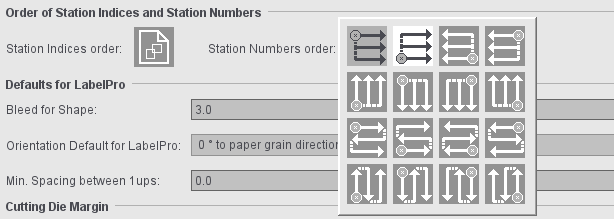
Order of indices and station numbers
Order of station indeces
By default, the order of indices as set in the CF2 file is used. You can choose another order as the default for new jobs by clicking the icon. You can set another order for each cutting die in the "Packaging" tab of the job.
In the "Packaging" mode, you can set the default order of station numbers. This presetting is effective when creating new jobs/job templates or product parts/product part templates in "Packaging", "> Sheet Optimization for Packaging" and "Montage" mode.
In the "Ganging optimization > Sheet Optimization for Packaging" mode, the sequence of the station numbers can also be specified in the "Packaging" step. This step is initially assigned the order of the station numbers from the default settings. If the sequence of the station numbers is changed, this has an immediate effect - without new optimization. When importing MIS JDFs, the order of the station numbers from the default settings is used.
This is where you can set defaults for creating new cutting dies.
•Bleed for shape
•Min. Spacing between 1ups
•Orientation Default for LabelPro: This lets you set an orientation default for the single 1ups. The following values are possible for the orientation default:
·0 degrees to paper grain direction
·0 degrees to cutting die
·90 degrees to paper grain direction
·90 degrees to cutting die
·180 degrees to paper grain direction
·180 degrees to cutting die
·270 degrees to paper grain direction
·270 degrees to cutting die
·0 or 180 degrees to paper grain direction
·0 or 180 degrees to cutting die
·90 or 270 degrees to paper grain direction
·90 or 270 degrees to cutting die
·0, 90, 180 or 270 degrees
·Free Rotation
The value for the orientation default then displays in the Nesting Wizard of LabelPro.
You can specify margins for cutting dies. This is where you can predefine them for the four margins (left, right, bottom, top). They are used as the default when new cutting dies are created. It is possible to customize them for a specific job in the "Packaging" and "Cutting Die" steps.

Note: In the case of cutting dies from program versions that do not support margins, the margins of these cutting dies will automatically be set to "0".
There are two different cases in the positioning of cutting dies:
•Jobs with all margins in all cutting dies with the value equal "0":
The cutting dies are positioned on the available space, evenly distributed.
•Jobs with at least one margin of a cutting die with a value unequal "0":
The cutting dies are positioned directly side by side taking into account the margins.
Handling of margins when generating new cutting dies via LabelPro
When a cutting die is generated via LabelPro (Nesting Wizard), the margins of the cutting dies are used as margins of the paper. The values are taken from the Preferences because there is still no cutting die when LabelPro is started. The values from the Preferences display in the Nesting Wizard after LabelPro starts.
CAM/CNC Machine (only with the "Label Pro" license)
For a CAM/CNC machine output in Label Pro, the files are written to the folder set here in the Preferences. The "CAM/CNC Machine" option must be enabled for this.
Machine Type: List box for selection of a CAM/CNC machine
Path for CAM: Folder where the file for the CAM/CNC machine will be filed.
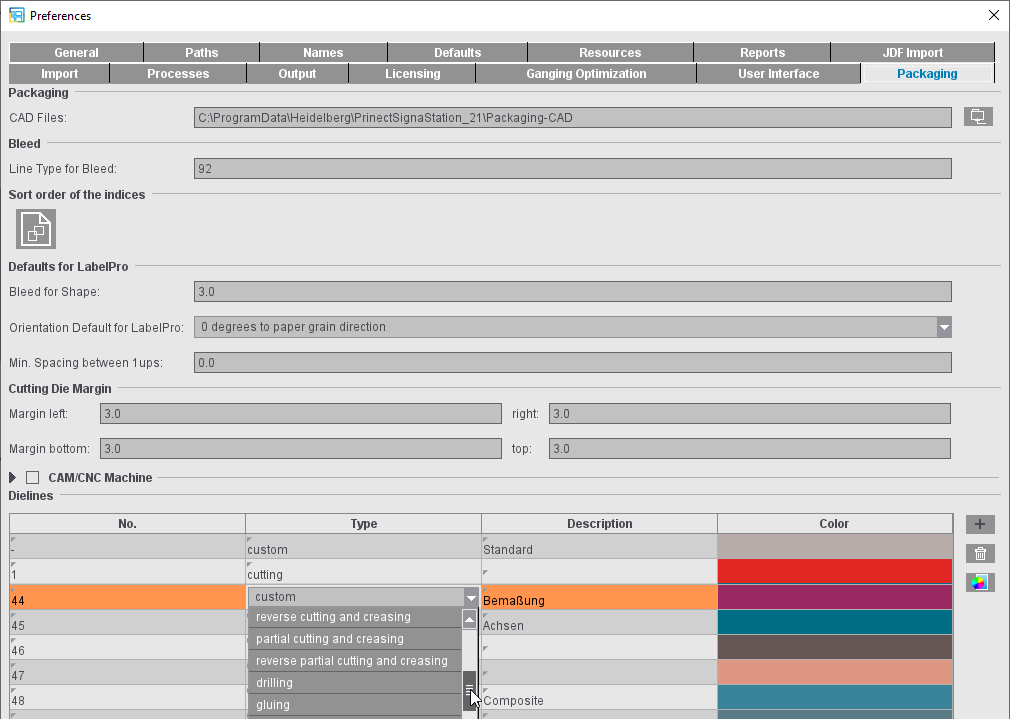
Dielines (only with the "Label Pro" license)
Register marks and cutting data are needed for the digital punch to be able to cut the 1ups correctly on the press sheet. Positioning of the laser is possible using the register marks. The cutting data are available in the CFF2 as lines with a predefined line type. In addition to cutting as a processing step, creasing, perforating and cutting and creasing are also possible as processing steps.
A CFF2 is available if a packaging job is processed in Signa Station. This CFF2 contains lines that are each assigned to a type.
In the Preferences, a processing step for finishing and a color can be assigned to the line type.
Embed CAD Cutting Die in Layout
Signa Station Supports the sending of CF2 lines for digital finishing processes such as contour cutting or creasing with process types and colors being assigned to the line types. With this option, the CAD cutting die is embedded into the layout for the workflow; in other words, the information is written to the JDF and sent to Cockpit.
Please note: In this context, Cockpit generates separations for each of the line types. The option is not suitable for finishing with conventional cutting tools. For this reason, the option is disabled by default.
The processing steps are assigned to a line number in the "Type" column by selecting one from a list with names compliant with the standard ISO19593-1.2. In the "Description" column, you can enter any explanatory text, for example, if you usually use a different name for the processing step.
You can create more line types using the plus button. You can remove line types that are not needed by marking them and clicking the trashcan button.
Register marks for later register of the sheet on the machine can be added automatically to the cutting die. "Cutting Die Register Marks" is available for this in the "Marks" step.
When Signa Station outputs a job like this in Cockpit, the line types assigned to processing steps and colors are written to the PDF marks layer with the full CFF2. In addition, the positions of the register marks are written to the JDF. In this process, all marks are considered register marks that have "Register Mark" as the mark type or were set as "Cutting Die Register Marks". In the JDF, these are in the layout compliant with the JDF specification.
In Cockpit, the additional colors "CFF2-Creasing" and "CFF2-Cutting" with "Tool" as the usage can be seen for finishing.
For output in Cockpit, there must be an ImpositionOutput or ImposedPrint sequence in addition to the Qualify sequence in "Processing". The "Tool" must be enabled in the setup for this so that the colors of the "Tool" usage are also included in the output.
You can open the PDF generated this way in Adobe Acrobat that shows the inserted optional content groups "CFF2-Cutting" and "CFF2-Creasing" as layers in the colors defined in Signa Station. Line types that are in the CFF2 but are not assigned to any concrete processing step can be grouped in the "CFF2-Unknown" optional content group.
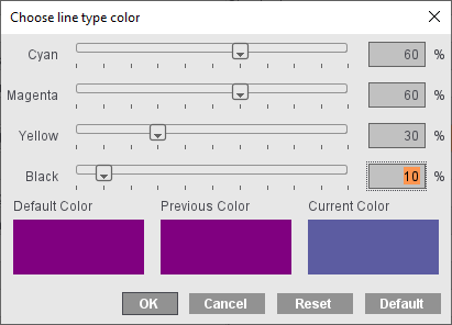
Display color
In addition, you can define the color that is used to display the line types.

|
To edit the colors, select the line color you want to change from the list and click the button with the color icon. |
The "Select Line Type Color" dialog then displays, where you can set the color you want using the slider or the text boxes. "Default" lets you reset the color values back to the original default settings, use "Reset" to restore the values last saved for a color.
In the "Output" tab, you will find the "Proof Attributes" and the "Default Screen Angles for RIPs" (in predecessor versions in the "Defaults" tab).
Colors for defined lines
You can set the color, width and type of line for the various profile lines. The unit in the "Line Width" column is equivalent to the standard unit of measure from the Preferences.
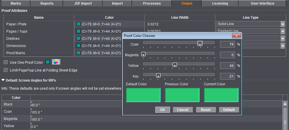
Use One Proof Color
You can select either a separate proof color for output of each of the listed line types or use the proof color you selected in this box for output of all line types.
Limit Page/1up Line to Folding Sheet Edge
The proof lines are drawn up to the sheet margin when this option is disabled. This can be become confusing if there are different-sized 1ups on one sheet. If the option is enabled, the proof lines are drawn only to just over their folding sheet edge, making it easier to assign the lines to the correct 1ups.
Default Screen Angles for RIPs
Settings in this group do not affect the HEIDELBERG workflow. The values are used only when you output to third-party RIPs.
More details can be found in Default Screen Angles in the Job Inspector.