The "Press Sheet" tab shows you a graphic of the press sheet of the product part currently selected, with all the objects placed on the press sheet.
You need the Press Sheet Inspector to edit a press sheet. The Press Sheet Inspector displays when you double-click the press sheet (or select it in the context-sensitive menu). A change in the inspectors window is also immediately seen in the graphic window in the "Press Sheet" tab.
You can display other press sheets in the product part in the graphic window by clicking them in the Browser window or list window. You open the Press Sheet Inspector when you double-click the press sheet.
•Display of the press sheet with the option of showing front and back at the same time. See Tile Front / Back.
•Ctrl + right/left arrow button: Switching between the views for front and back (helpful, for example, when working with the option "Place all 1ups with front/back swapped") as well as between press sheet variants and press sheets with rolls.
•Positioning of elements by dragging-and-dropping them from the Browser window or list window. More details can be found in Drag-and-Drop.
•Import of pages to different layers. See View Properties and Enable/Disable Layers .
•Creation of "internal marks" for the job currently open. See Creating Internal Marks.
•Configuration of the graphic view as you like it and display of the units of measure for objects. See View Properties and Enable/Disable Layers .
•Selection of color layers. See Channel.
•Setting zero on the ruler
See Mouse and Keyboard Shortcuts in Graphic Window.
•Working with measure tools.
See Mouse and Keyboard Shortcuts in Graphic Window.
•Setting magnetic snap lines
See Mouse and Keyboard Shortcuts in Graphic Window.
Functionality Using the Context-sensitive Menu
The following functions are available when you display the context-sensitive menu in the "Press Sheet" tab in the graphic window:
"Press Sheet Inspector"
Displays the Press Sheet Inspector in the inspectors window.
"Print Press Sheet..."
Prints the currently selected press sheet. The "Print Job ..." window displays.
"Delete Press Sheet"

Prerequisite: Can only be selected in the "Ganging Optimization" work mode.
Deletes the selected press sheet; a press sheet must still remain in the job.
"Folding Sheet Inspector / Assembly Block Inspector / Cutting Die Inspector"
Displays the Folding Sheet Inspector or the Assembly Block Inspector in the inspectors window.
"Align"

Prerequisite: Can only be selected in the "Montage" work mode.
The "Align" command is available in the context menu if at least two assembly blocks/folding sheets are selected.
You select and deselect assembly blocks with the shortcut "command key + mouse click".
Alignment to the edges of the block selected first is possible either to the right, left, top or bottom. You can also align the selected blocks horizontally or vertically to a center axis, e.g. to be able to crease a common zero line.
"AutoArrange Folding Sheets.../AutoArrange Assembly Blocks..."

Prerequisite: Can only be selected in the "Imposition" and "Montage" work modes.
The folding sheets/assembly blocks can be rearranged automatically but also manually by entering gap data.
"Swap Front and Back Folding Sheet/Assembly Block/Cutting Die"

Prerequisite: Front and back must have been defined. This function is not designed for "Work-and-tumble" or "Work-and-turn".
You can, for example, match plates to certain colors with this function. Multiple selection is possible!
"Swap Folding Sheet"

Prerequisite: Can only be selected in the "Imposition" work mode.
You can, for example, match plates to certain colors with this function.

Prerequisite: Can only be selected in the "Imposition" work mode.
You can, for example, match plates to certain colors with this function.
"Delete folding sheet/assembly block"

Prerequisite: Can only be selected in the "Imposition" and "Montage" work modes.
Deletes the active folding sheet/assembly block.
"Create new assembly block"

Prerequisite: Can only be selected in the "Montage" work mode.
Creates a new assembly block. This function is identical to that in the Assembly Block Inspector .
"Duplicate Assembly Block"

Prerequisite: Can only be selected in the "Montage" work mode.
The active assembly block with all its contents is duplicated. The duplicated assembly block lies directly on top of the original assembly block.

Note: Changes to a duplicate (size, 1up copies,...) are mapped immediately to the other duplicates if this makes sense. The parameters in "Position X" and "Position Y" are applicable only for the selected block and also the various margins ("Left Margin", ...) refer only to the active assembly block. The reason for this is that some MIS systems define the position of the various duplicates on the sheet by assigning different margins and, for that reason, different margins must be possible.
"Change Station Index..."
Also found in the "Assembly Block" and "Cutting Die" tabs. See "Change Station Index and Article..." for details.
This function is designed to let you manually assign jobs from the "gang pool" to a press sheet, especially as a supplement to a sheet optimization that was already run.

Prerequisite: Can only be used in the "Gang Job" workflow.
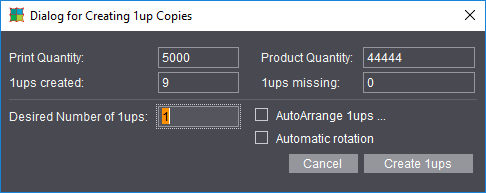
The dialog shows the current "Print Quantity", the "Product Quantity", the 1ups created and the 1ups still missing for the set print and product quantities.
In "Desired Number of 1ups" you can set how many 1ups will be created after you click "Create 1ups". The new 1ups are placed near the selected 1up and generally overlap.
"AutoArrange 1ups": The "AutoArrange Properties" dialog opens.
"Automatic rotation": The parameter is automatically set in the dialog shown above.
You can remove assembly blocks from the press sheet using "Delete Assembly Block" in the context-sensitive menu. Multiple selection is possible. One of the assembly blocks has "Master Label" as its attribute. If you delete the master label, then all ups of this kind will be deleted (following query).
"Fit Marks and Bleeds"
Signa Station checks the spacing between the folding sheets or assembly blocks on the selected press sheet. Cut marks and/or bleed are automatically deleted if they overlap in adjacent blocks.
It's a good idea to use this function after moving blocks manually because overlapping elements can be overlooked in the graphic window.
In addition, the color control mark is fit to the subject (AutoClip to subject).
"Marks"
"Enable Clip Path"
The clip path of a mark is now active and displayed accordingly. A mark with a clip path is highlighted by a blue line. The clip path is highlighted by a green/black line if a mark is selected.
"Disable Clip Path"
The clip path of a selected mark is ignored.
"Edit Mark..."
You can open and edit a selected mark with the relevant editor for that mark.
For details, see the relevant marks editors in the Editors chapter or Working with marks - Introduction.
You can duplicate one or more selected marks. The "Duplicate Mark..." window opens where you can enter the following data:
- Number of copies you want to create
- Offset of the copies in horizontal direction (X)
- Offset of the copies in vertical direction (Y)
It's also possible to enter negative values for an offset.
"Delete Mark"
The mark you selected is deleted after you confirm an alert message.
"Graphic"
"Save as..."
You can save the current press sheet as a graphic file in the Portable Network Graphics Format (.png).
"Print..."
You can output a copy of the current press sheet to a printer.
"Print All..."
You can output a copy of each press sheet in the job to a printer.
"Delete Page Assignment"
Deletes assignment of the selected page(s) in the job. The pages/1ups in the job no longer have any assigned content.
"Paste Pages from Clipboard"
The function is active only if a page/1up was copied to the clipboard beforehand in the "Contents" step. You can then paste it to any position you want. See "Paste Pages from Clipboard".
"Assign Station Numbers..."

Prerequisite: Can only be selected in the "Montage" and "Packaging" working modes.
The function only works in conjunction with the "StationNumber" mark. See Step 1: Assigning the 'StationNumber' mark to the 1up and Step 2: Assigning the station numbers to learn how to use and handle this function.
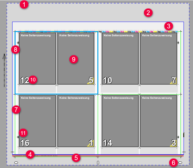
1.Blue-and-white line
Marks the maximum imaging window. The imaging window is based on the properties of the selected filmsetter or platesetter types.
2.Gray area (color can be selected)
Marks the plate size. This is based on the plate size defined in the plate template.
3.White area (color can be selected)
Marks the defined paper size. The paper size is defined in the "Plates" step.
4.Blue line
Marks the lead edge of print (baseline + gripper margin)
5.Red bars (color can be selected)
Indicates the gripper margin and/or the print area together with the blue line.
6.White punches
Displays the press punches. The punches are only symbolic and don't reflect the shape they really have at the press.
7.Green line
Marks the defined paper margin (cut block) of the folding sheets / assembly blocks.
8.Light blue line
An object is selected and can be moved manually, for example when you click in the graphic window.
An object can be a folding sheet, assembly block, page or a mark.
You first select a folding sheet in the graphic window > "Press Sheet". After this, you can select a page on the folding sheet with another click.
9.Gray area (pages)
Marks the page (imposition) or 1up (montage). The light gray area around the page or 1up indicates the trim.
10.Page numbers
•White/black numbers: The page number is white if pages are not assigned and with a gray background. The page number is black if pages with or without a preview are assigned. Magenta marks without a preview.
•Green page number: The page numbers of special master pages and tiles are green to tell them apart more easily.
•Red page number: The page numbers are red to see them better if "Creeping" is active in the Page Inspector or globally in the product part.
11.Marks: You can move manually placed marks as well as some automarks directly in the graphic view after clicking them with the left mouse button held down (orange or magenta frame). Marks that have a red frame when you click them are automarks that cannot be moved (see Editing Automarks in the Graphic View).
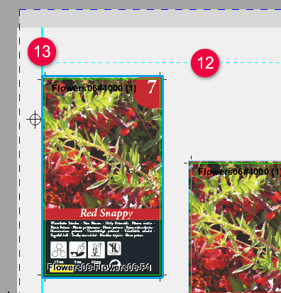
12.Cyan line (dashed)
Identifies the area for optimization specified by the geometry data (margins) in the case of ganging optimization jobs.
13.Cyan line (solid)
Indicates snapping to the edge of the optimization area when an object is moved interactively (for ganging optimization jobs without layout default).
Improved operation during manual layout editing in the graphic view ("magnetism")
During sheet layout editing, the layout may be completely redrawn. Particularly with low zoom levels and many closely spaced folded sheets/pages, precisely creating the layout and positioning the elements manually is often difficult. To facilitate positioning, objects snap into place in different places when they are moved manually.
Magnetism is also supported in the folding sheet, assembly block and cutting die views.
Depending on the selected magnetism mode, the situation and the objects to be placed, snapping takes place either at the edges of the reference objects or at corner points.
Magnetic lines
When you move folding objects in the graphic view, other objects generate guides to which the active object snaps. This makes it easier to align objects during manual positioning.
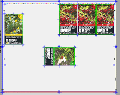
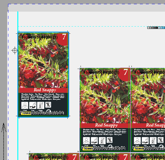
Example (1 = 1up that is being moved, with blue frame):
•A: Snap to horizontal line (yellow), the reference 1up (2) also has a yellow background (multiple reference 1ups in this example)
•B: Snap to vertical line (cyan), the reference 1up (3) has a cyan background
•C: Snap to horizontal (yellow) and vertical (cyan) lines; the reference 1up (4) has a green background
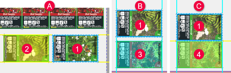

Note: If both the top and bottom edges, or the right and left edges are within the snap range of another element, both guides are displayed.
Magnetic points
Snapping does not always take place at the edges of other objects or at snap lines, but also at the corners of a neighboring object, depending on the mode. When working in this way, no lines are displayed, but the snapping points are marked. In addition, the "snap radius" is greater than with standard snapping.
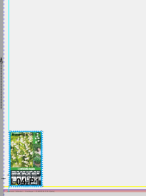
Example:
In the mode "From bottom left, horizontal". the moved object (blue dashed border) snaps to the bottom right corner of the left object.
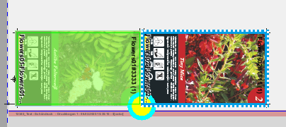
Snapping is indicated by a targeting circle.
Magnetism at a reference point
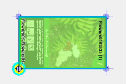
In the case of magnetism at a reference point, e.g. by moving a mark, magnetism is represented by a magnetic point. In addition, the object associated with the reference point is highlighted graphically. This extended display also occurs when adding a mark from the corresponding inspector via drag and drop.
In the case of magnetism at a reference point using the frame tool, magnetism is represented by a magnetic point. In addition, the object associated with the reference point is highlighted graphically.
In the case of magnetism at a reference point when setting the zero point, magnetism is also represented by a magnetic point. The display of the reference points is switched on automatically and switched off after the zero point has been set.
"Show Non-printable Margins" option enabled: additional reference points are inserted for the printable area, which can also be snapped to. In addition, the corresponding object, in this case the printable area, is highlighted graphically.
If one of the two selection tools is active, the snap-in mode can be set differently with an additional button. In the default setting, snapping to adjacent elements is possible in all directions (see description in the previous section), i.e. all edges are taken into account.
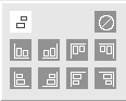
Clicking the button opens a selection of buttons that can be used to control the snapping function. You can choose from which corner you want to rebuild the layout and in which direction.
The buttons in the top row limit snapping to the horizontal direction; consequently, the elements are placed next to each other and aligned to the top/bottom edges.
The buttons in the bottom row limit snapping to the vertical direction,; consequently, elements are placed below/above each other and aligned to the left/right edges.
This work mode lets you create the layout manually and in a controlled manner.
Button functions

|
You can use the "m" key to switch between the two buttons in the bottom and top rows (shown here: alignment from the bottom left), that is, from horizontal to vertical alignment. |

|
The button at the top left can be used to switch back to standard snapping with guides. The "n" key can be used to switch between standard snapping with guide lines and targeted alignment, |

|
The button at the top right can be used to disable snapping completely. |
Keyboard commands
The "o" key can be used to switch magnetism on and off in the graphical view.
In the case of magnetism at reference points, it can be helpful to display the reference points to make them easier to find. To do this, the "R" key can be used to show or hide all reference points.
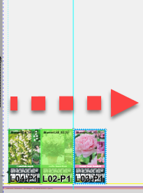
Example: Building the layout from the lower left corner.
|
The first folding sheet is placed in the lower left corner. |
|
|
|
Switch to the "from lower left horizontal" mode. Now you can place the other folding sheets to the right of the first one, snapping only affects the top/bottom and right edge respectively. |

|
|
|
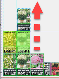
When you have finished building the bottom row: Switch to the "from lower left vertical" mode. Now you can place the other folding sheets above the bottom row, snapping only affects the right/left and the respective top edge of the bottom row.
|

|
|
Save magnetism mode as default mode
"View Properties" > "Magnetism" indicates the currently selected magnetism mode. To use this magnetism mode, click the button "Save as Default": this setting then applies to all new jobs.
When positioning the folding sheets, it is often desirable to work starting from the lay edge of the press sheet. For this reason, the magnetism mode can be switched automatically depending on the lay edge. The same edge of the position of the lay edge is used as the pull lay.
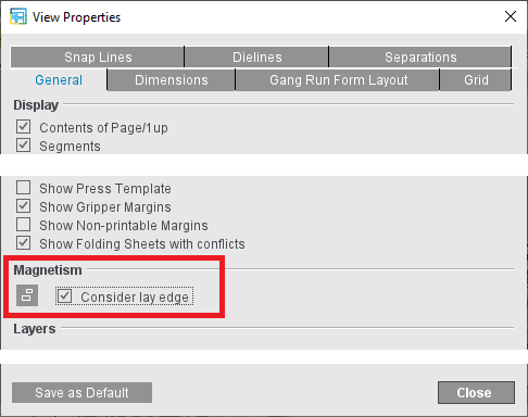
For this purpose, enable "Heed lay edge" in "View Properties". This automatically switches the magnetism mode for each press sheet depending on the position of the pull lay. You can save this setting as a default as well.
Example: The set magnetism mode is set to lower left with horizontal orientation. If a change is also made to a press sheet with the pull lay on the right side and thus the lay edge on the right side, the mode switches to lower right with horizontal alignment, i.e. sheet layout from right to left.
Multiple selection
If a folded sheet or a page is clicked in the graphic view, only this object is selected, even if the object of this job is placed several times on the press sheet. When the job is selected in the input list, all objects of this job are highlighted.
You can now do this also in the graphic view by simultaneously pressing a key:
|
Key |
Action when clicking |
|
Shift |
Selects all articles of a job (analog to the selection in the input list) |
|
Ctrl |
Add another single article or remove it from the selection |
|
Shift + Ctrl |
Add all articles of a second job to the selection |

Note: The key shortcut Shift + Ctrl for changing the graphic tool for the measuring frame is no longer needed.
Snap function at the margin of the optimization area
For ganging jobs, 1ups also snap to the optimization margin, i.e. the area defined by "Geometry Data for Sheet Optimization", when they are moved. This only applies to ganging jobs in the "Sheet Optimization without Layout Default" mode (see 12/13 in Display and Functions).
Warning if elements overlap
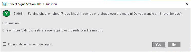
When moved manually, elements may overlap or be placed on the margin. To detect these errors in good time, you can activate the "Show overlapping sheets/mounting blocks" option in the settings for the graphics view.
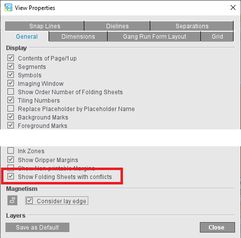
If the option is enabled, elements are marked in red and with a warning symbol if they overlap and/or lie on the margin. In addition, a corresponding text message is displayed below the graphic view:
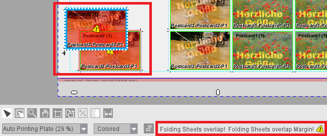
If the sheet is output without correction, you will receive a warning again during output::