
Setting up a Data Terminal device in Cockpit
Short overview of required steps:
1.Set up Data Terminal users with personal data (employee ID, second name, first name) in the user administration of Prinect Cockpit.
2.Assign the user to at least one user group (see How do I assign a user the permissions of a certain permissions group?).
3.Set up new "CDM devices" for each Data Terminal workstation in "System" (see Setting up a Data Terminal device).
4.The appropriate sequence is created automatically ("SheetfedPrinting" type, for example) (see also "Sheetfed Printing" Sequence Template). This is only necessary for the "sheet-fed" device type.
5.The PPF import configuration is created automatically (see also Create/configure a process). This is only necessary for the "sheet-fed" device type and only if the PPF import is to be used.
6.Install the Data Terminal software on the respective workstations (URL: http://name of Prinect server:6361/DTService-J).
You must take the following steps to be able to use the Data Terminal:
1.Define a user on the Prinect server
You must define a user and enter the following attributes in the "Person" section:
·Employee ID
·First name
·Surname
2.Assign a user to a user group
The user you have just defined must at least be assigned to the user group "*Operator", "*Assistant" or "*MultiUser". For example "PostpressOperator" (for the "Operator" function; see Functions), "PostpressAssistent" (for the "Assistant" function) or "PostPressMultiUser" (for the "Multiple operator" function).
Background: A user group is assigned to each Data Terminal device when it is defined. Only users belonging to this user group can log in to this Data Terminal device.
The defined users appear on the Data Terminal in a user list having the above-mentioned attributes.
Note: Only persons who have been correctly defined on the Prinect server can log in to the Data Terminal. See How do I create a new user account? for details on how to create a new user.
3.Set up the Data Terminal device on the Prinect server.
A Data Terminal device must be defined on the Prinect server. The Prinect server needs to know what type of device it is (prepress machine, press, postpress or manual workplaces) and where it should send the job data to. The devices are displayed in the Data Terminal in the "Workplaces settings" menu. If you have installed the Data Terminal on several workstations, you have to set up the desired devices for each Data Terminal.
4.A new sequence, for example "SheetfedPrinting", is created automatically.

Note: Only necessary for the "Sheet-fed printing" device type.
For more information on this sequence, see "Sheetfed Printing" Sequence Template.
5.The PPF import configuration is generated automatically.

Note: Only necessary for the "Sheet-fed printing" device type.
The PPF input directory is necessary so that the jobs can also be sent from the Prinect server to the Data Terminal.
Refer to Create/configure a process for more information on how to configure the automatically created PPF input directory.
6.Install.
7.Activate the devices on the Data Terminal (see Activating a Data Terminal device).
Setting up a Data Terminal device
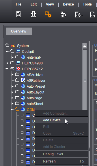
Set up a Data Terminal device with the CDM in the System Settings, regardless of the device type. Run the Device Assistant with the "Add Device..." item in the context menu.

Device classes
In "Device Class", select the machine type to connect via the Data Terminal device. For an overview of device classes, see Device class.
Connection
In step 1 of the Device Assistant, specify a Data Terminal connection or a Data Terminal connection with counter box in "Connection".
•Data Terminal
Use this connection type for machines and manual workplaces which cannot be connected online.
•Data Terminal counter box
Use this connection type if you use machines which transfer the totalizer reading to the Data Terminal via a counter box. In this case you do not need to manually enter the quantity produced at the Data Terminal. You can connect up to six machines per counter box.
You will find more details in Additional configuration of the Data Terminal device with counter box.
•Data Terminal with direct connection of the machine
This connection type is available for device classes "Cutter" and "Digital Printing". Machines of these device classes can be connected directly, but there is no feedback of operating data. An additional Data Terminal is used for the PDC messages (operations).
Refer to Connecting Digital Presses on how to connect a digital press.
Refer to Connection of Polar Cutter on how to connect a cutter.
Contents of operations list
Here you can specify whether the Data Terminal device is to list only operations that can be executed or also those that have already been scheduled for the device.
For more details, see Contents of operations list.
•Start stop absolute quantity
Select this time recording mode if you wish to record the production times in "real time" when processing a job. In other words: you start a work step (such as "Setup") by starting the operation (PDC message). "Setup" will end as soon as you start the next work step (such as "Folding").
The time elapsing between "Setup" start and "Folding" start is captured as setup time.
•Time
Select this time recording mode if you only wish to record the duration of an activity when processing a job. This means that only the total time of an activity is recorded. This is only done once you have completed the activity.
For more details, see Time Recording Modes.
Book Unscheduled Only to Jobs
You enable this option, for example, for Data Terminal devices that you do not wish to plan in the Scheduler. With this option enabled, the "Jobs" column of Data Terminal shows only unscheduled jobs.
Assigning functions
You can assign several functions to the Data Terminal device like with direct connection.
This means you define who can log in to the machine. The "Operator" function is activated by default and cannot be deactivated.
Activate the "Assistant" function if assistants work on the machine in addition to the operator.
Enable "Multiple Operator" if someone is working on several machines at the same time. This is generally not the case for presses. A multiple operator is mainly used for finishing machines.
See Assigning functions for a more detailed description of the functions.

Note: The times appear as overlapping production in the time sheet and in Analyze Point. The Business Manager displays open entries.
Deviating configuration when creating a Data Terminal device from the "sheet-fed press" device class
Except for a few additional parameters to be defined, the creation of a Data Terminal device with the "Sheet-fed press" device class is identical to a Data Terminal device of another device class. Proceed as described in Device Assistant - "Assigning operation groups" and "Assigning operations" if you do not want to set up a "sheet-fed press".
Only the differences are described below.
•Defining the device class and connection type
•Defining the number of printing units and options
Defining the device class and connection type
Choose the "Sheet-fed press" item in the "Device class" area. All other options are identical with the other device classes.
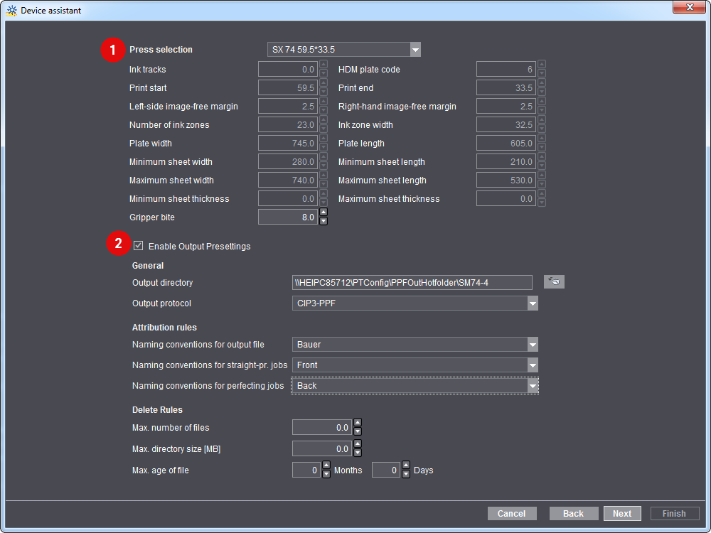
Select the press you wish to connect (1). Only presses that have already been created in the master data store are displayed.
Enable the "Enable Output Presettings" (2) option if you want to generate machine presettings.
With the option enabled, press presettings are made available in addition to production data collection. Here, you set up the necessary output directory.
For details, see Configure generation of presetting data
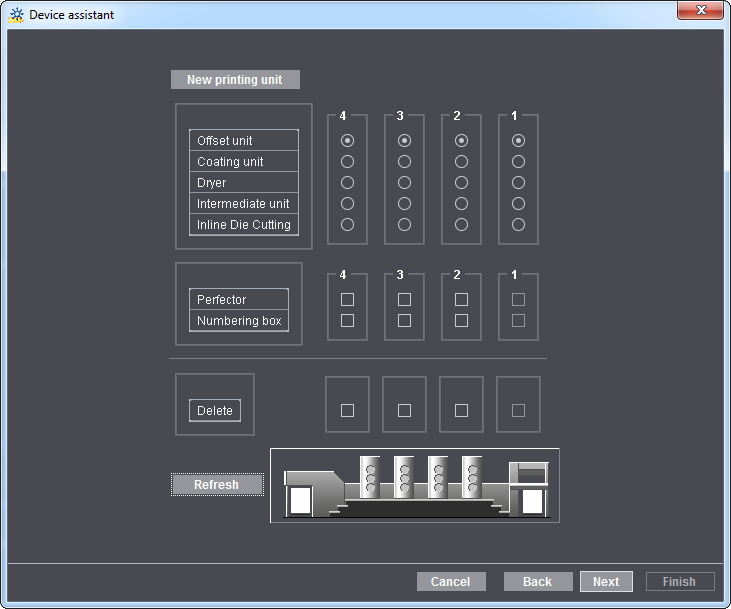
Defining the number of printing units and options
Here you can "model" a copy of your printing press. This model is important, as it is used to calculate how many passes are needed on the printing press for jobs when they arrive. For example, if you have an 8-color press without perfector and wish to print a 4/4 job, you will need two passes. With a perfector you would only need one pass.
Device Assistant - "Assigning operation groups" and "Assigning operations"
In the next two steps of the Device Assistant, you select the operation groups and their respective operations. The operator can then select these at the Data Terminal and submit them to Analyze Point.
In the Device Configuration, you specify the operation groups and operations available for selection. See Operation Groups (Cost Groups).
The assignment of operations is selected for each function (operator, assistant and multiple user) individually.
Device Assistant - Assigning User Groups
In the "Assigning User Groups" area, functions are assigned to user groups who are permitted to log in at the Data Terminal device.
•At least the "*Operator" user group is assigned to the operator. For example, "PostpressOperator".
•The "*Assistant" user group must be assigned to the assistant.
•The "*MultiUser" user group must be assigned to the multiple operator.
Device Assistant - Creating Variants
A variant is understood to mean a machine configuration which is comprised of individual modules. Depending on the device type selected, different modules are available for compiling a variant.
In the case of the saddlestitcher, for example:
•Variant_1 consists only of the "Gathering" module.
•Variant_2 consists of the "Stitching" module and the "Three-knife trimmer" module.
•Variant_3 consists of the modules "Gathering", "Stitching" and "Three-knife trimmer".
Different variants are required in finishing, in particular depending on the type of job to be processed.
In order for the production costs to be calculated in accordance with the variant used, each variant is assigned to its own cost center. The cost centers (see Cost Centers ) have to be defined in advance and aligned with the connected Management Information System.
•Variant_1 is assigned to the cost center "5300, saddlestitcher 1".
•Variant_2 is assigned to the cost center "5310, saddlestitcher 2".
•Variant_3 is assigned to the cost center "5320, saddlestitcher 3".
If you now load a job on the Data Terminal, you have to select the variant with which you are producing the job.
One operation can, for example, comprise the steps of gathering, stitching, inserting and trimming. However, the selected variant only comprises the "Stitching" and "Three-knife trimming" modules. What effects the selection of a variant has for the processing of an operation is described on the basis of an example in the "Working with jobs" chapter of the Data Terminal operating manual.
For information about the variants, see the Setting up variants.
In the last step of the Device Assistant, you set the default values for "Default setup operation" and "Default operation for assistant" in the lower part of the window.
Explanation: There are machines on which a login is not necessary in order to start a job. Furthermore, activities which have been performed on the machine do not necessarily have to be reported back manually. For example, the job can be loaded on the machine, the machine started up, and the job started without recording an operation (PDC message). For the evaluation, however, it is necessary for the machine operator and status messages to be recorded for a job. That is why you define operations (PDC messages) here which are generated automatically when the activities carried out on the machine are not recorded manually.
Default operation for assistant: Only visible if you activated the "Assistant" function when assigning functions. This is where you can define which PDC message is automatically generated for the assistant if a user logs in to this device in the "Operator" function and loads an operation. The operation (PDC message) is also generated if the user logs off this device and logs on to another device in the "Operator" function. This means that the assistant is automatically logged in to the device and that this does not have to be done manually by the assistant.
In the "Summary" dialog of the Device Assistant, you can enable the "pallet sheet" like with a press connected online. For a more detailed description see Creating a plate set sheet.
Additional configuration of the Data Terminal device with counter box
With the exception of the additional "Counter box configuration" dialog window, the procedure for defining a Data Terminal device with counter box is identical to the procedure for defining a Data Terminal device without counter box (see Setting up a Data Terminal device).
Only the differences to defining a Data Terminal device without counter box are described here.
Connection type
The "Data Terminal with counter box" entry must be selected in the "Connection" list box.
The "Counter box configuration" dialog
Here you have to define how the totalizer reading of the machine's counter box of the machine is transferred.
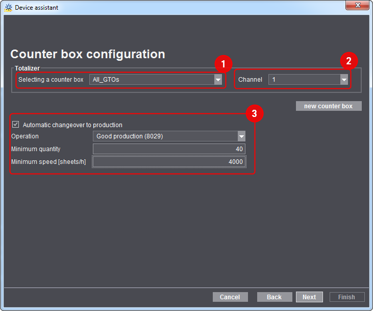
The general procedure is as follows:
•Selecting a counter box (1)
This list box offers all counter boxes set up in the Device Configuration. You can also make a counter box with the "new counter box" button. See Creating a New Counter Box.
•Assign a channel (2) to the new machine (device).
There are 6 channels for each counter box. One for each connected device.
•Enable/disable the option "Automatic changeover to production" (3).
You can use this option to automatically change over to "Production" (good production) as soon as the conditions set here are fulfilled. This means that the "Production run" (start good production) does not need to be recorded manually.
The "Operation" list box contains all operations assigned to the device. A suitable operation must be selected so that the "Automatic changeover to production" can be executed.
The following two parameters must always be fulfilled at the same time:
·minimum quantity set
·minimum speed set
This means that the machine does not change over to "Production" until a quantity of 10 sheets was processed at a speed of 4,000 [sheets/h], for example. The machine does not change over to "Production" if one of the two parameters deviates from the settings.
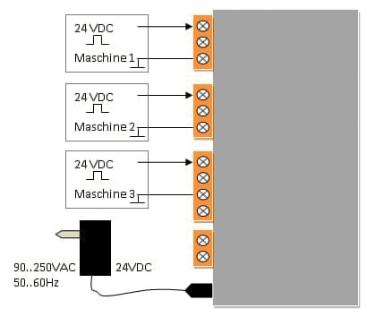
The procedure for carrying out the electrical wiring of the counter box on a Heidelberg machine depends on the machine. The wiring diagrams for two machine variants are shown below.
You can find a detailed description of the counter box in the IPCAS manual supplied with the counter box. For the two most important points we have found the corresponding chapters from the IPCAS manual for you:
•IP address of counter box: Chapter 3: Start-up
•Installation of counter box: Chapter 9.4: Connector pin-out
Variant 1
The machine has a 24 VDC sensor/light barrier output. For this variant a maximum of three machines can be connected.

Caution: The ground (GND) connections must not be bypassed. Never bypass the ground connections of two machines.
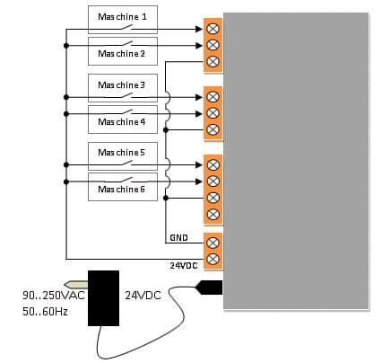
Variant 2
The machine has a floating switching contact. For this variant a maximum of six machines can be connected.
How can I tell if the Data Terminal device is working correctly?
1.Start the Data Terminal on the computer for which you have defined the device.
2.Start the Prinect Cockpit on the Prinect server or a client.
3.Go to "Queues".
The "CDM" engine should now be listed in the "Engine" column and the previously entered "Device name" in the "Queue" column. In our example this is "KH_78".
The "Status" column must say "Started".